Category: How to
-
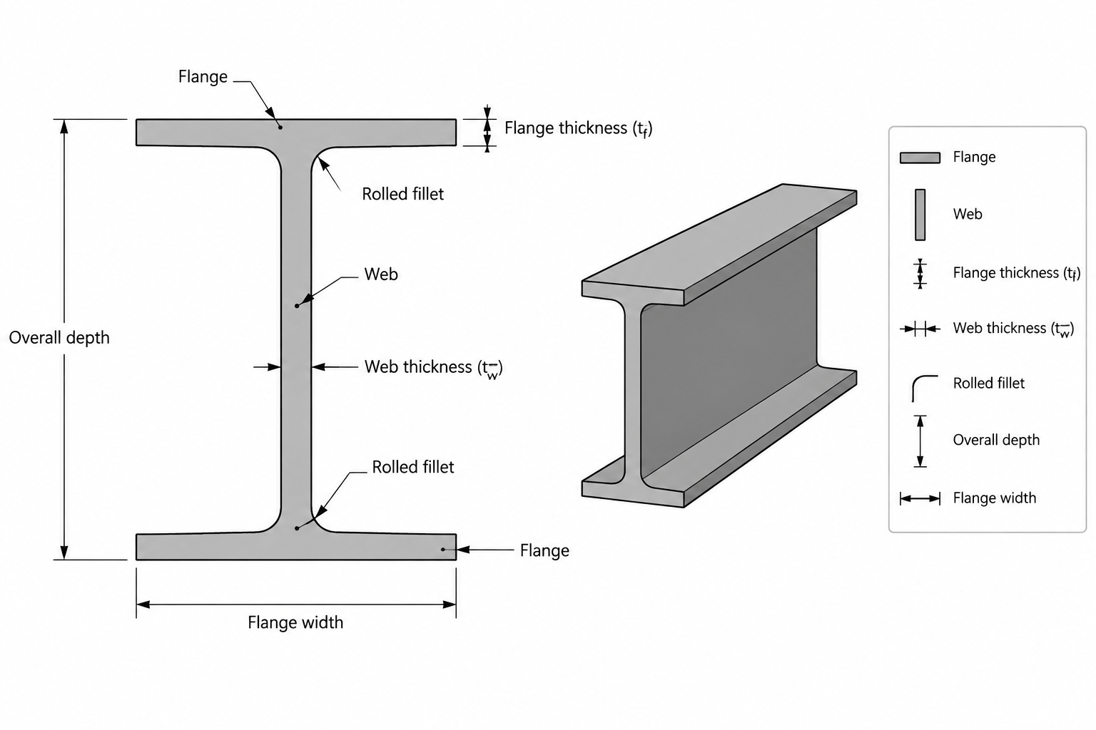
Rolled Shapes vs. Built-Up Steel Members: How to Read, Model, and Detail the Difference
Learn how rolled shapes differ from built-up steel members, how each appears on structural drawings, and what drafters should verify before modeling or fabrication.
Written by
-
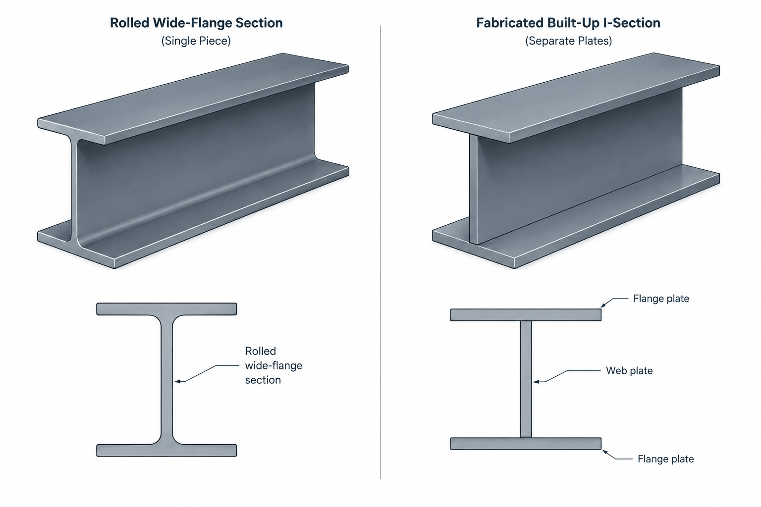
How to Use Structural Steel Shape CAD Blocks Without Losing Dimensional Control
A practical workflow for selecting, checking, scaling, placing, and managing structural steel shape CAD blocks in engineering and detailing drawings.
Written by
-
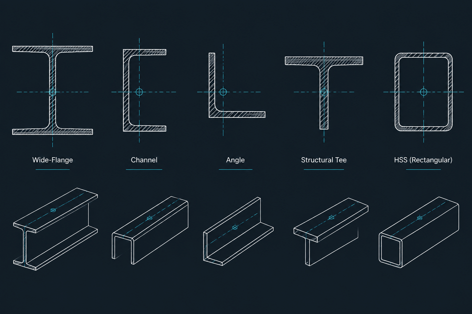
Why W-Shapes in the Same Nominal Depth Series Do Not Line Up
Learn why W-shapes in one nominal depth series can have different actual depths, flange geometry, elevations, and connection detailing requirements.
Written by
-
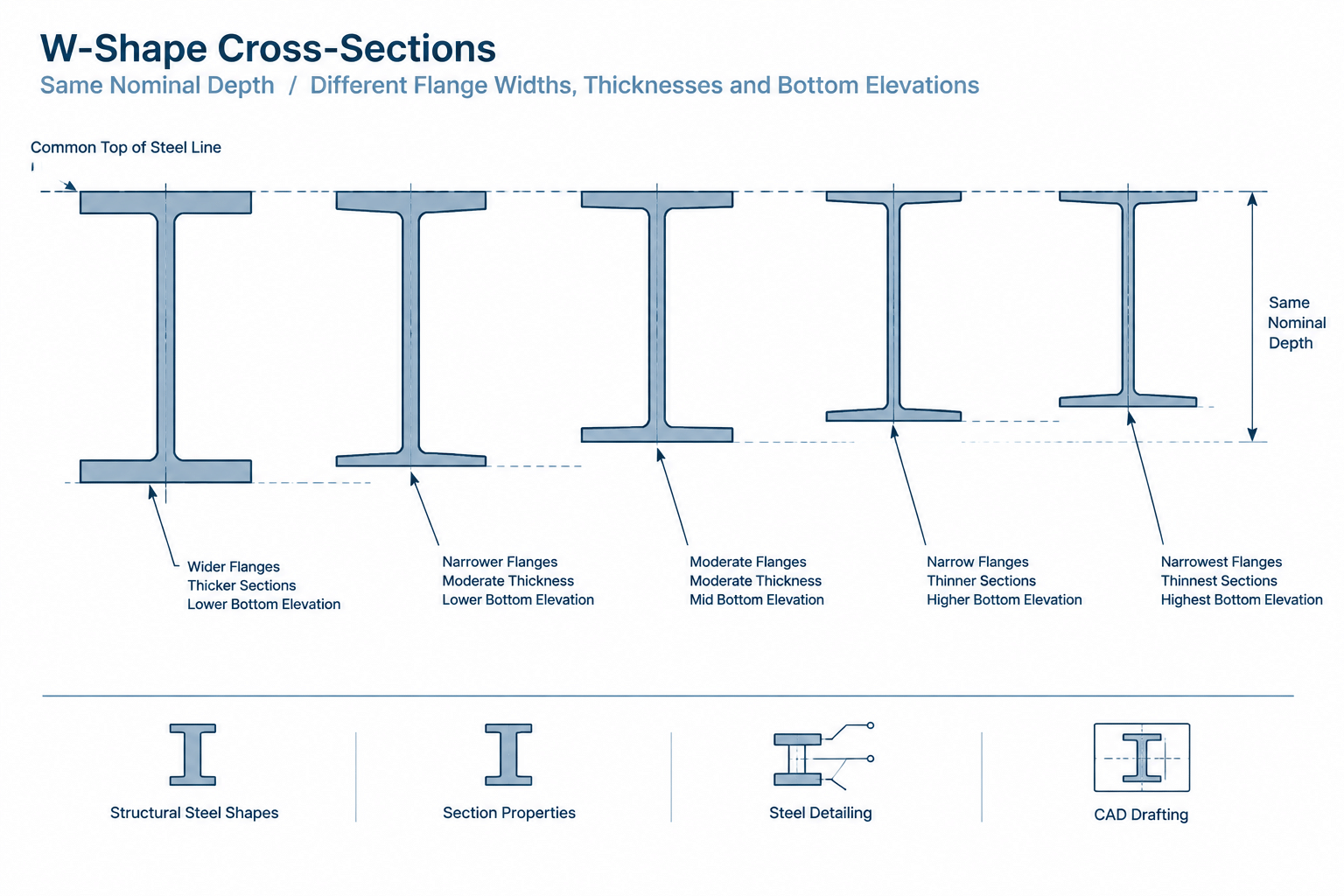
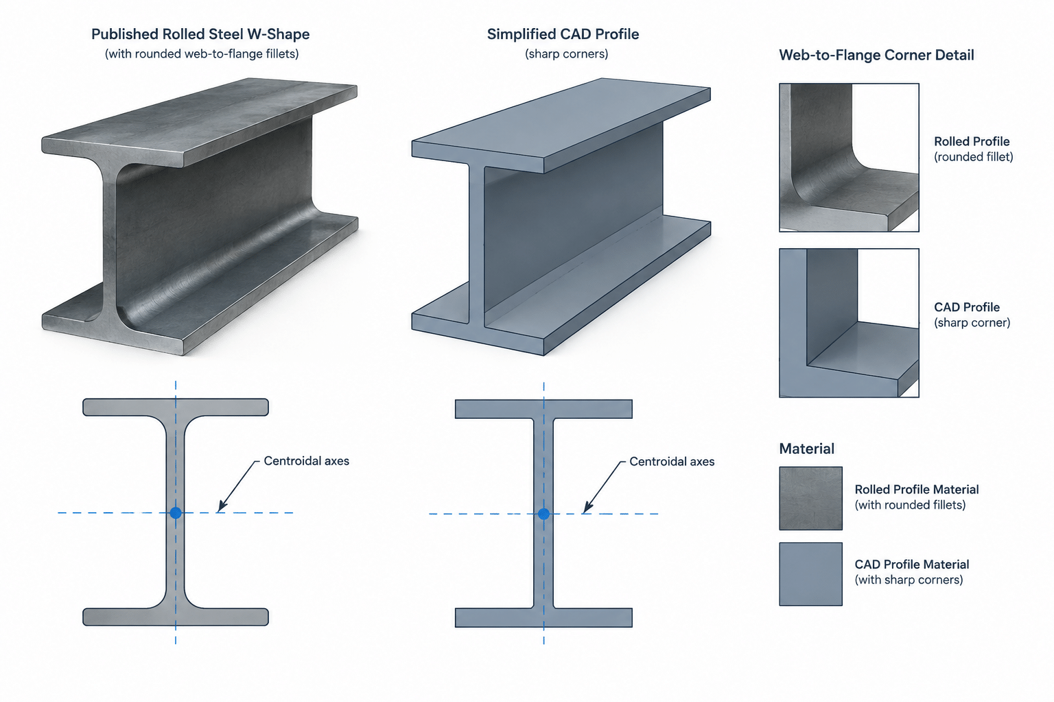
Why CAD-Calculated Steel Section Properties May Not Match Published Shape Tables
Learn why area, centroid, inertia, and other properties calculated from CAD profiles can differ from published structural steel shape tables.
Written by
-
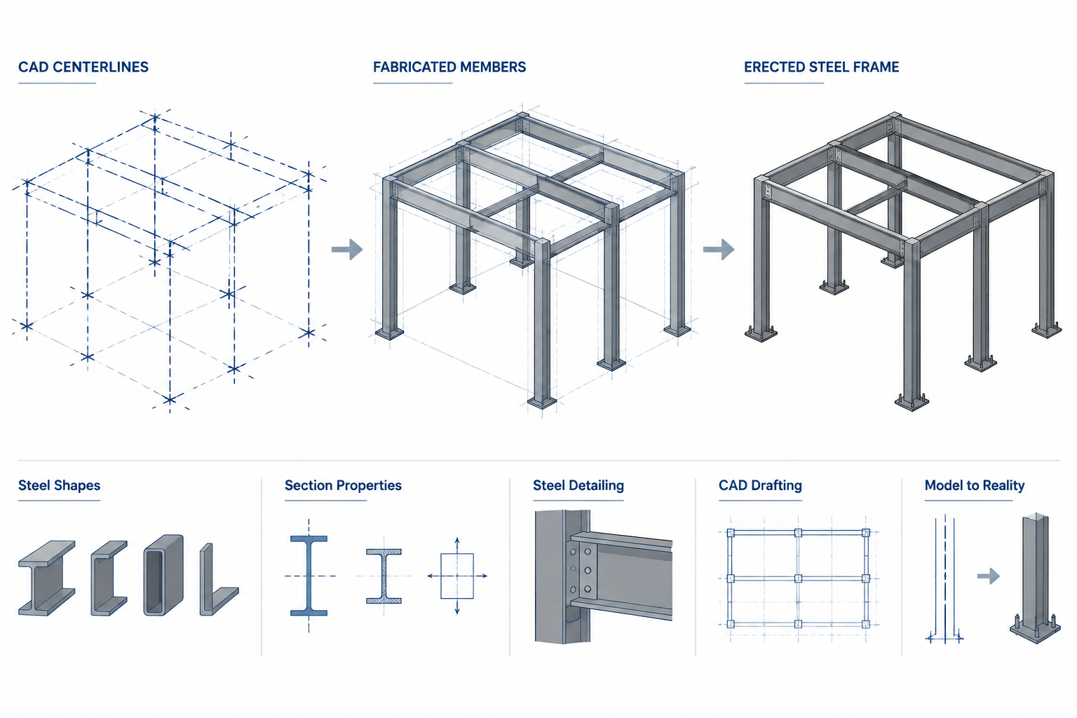
Mill, Fabrication, and Erection Tolerances in Structural Steel Detailing
Learn how mill, fabrication, and erection tolerances differ, and how to account for real steel geometry in drawings, CAD models, connections, and fit-up.
Written by
-
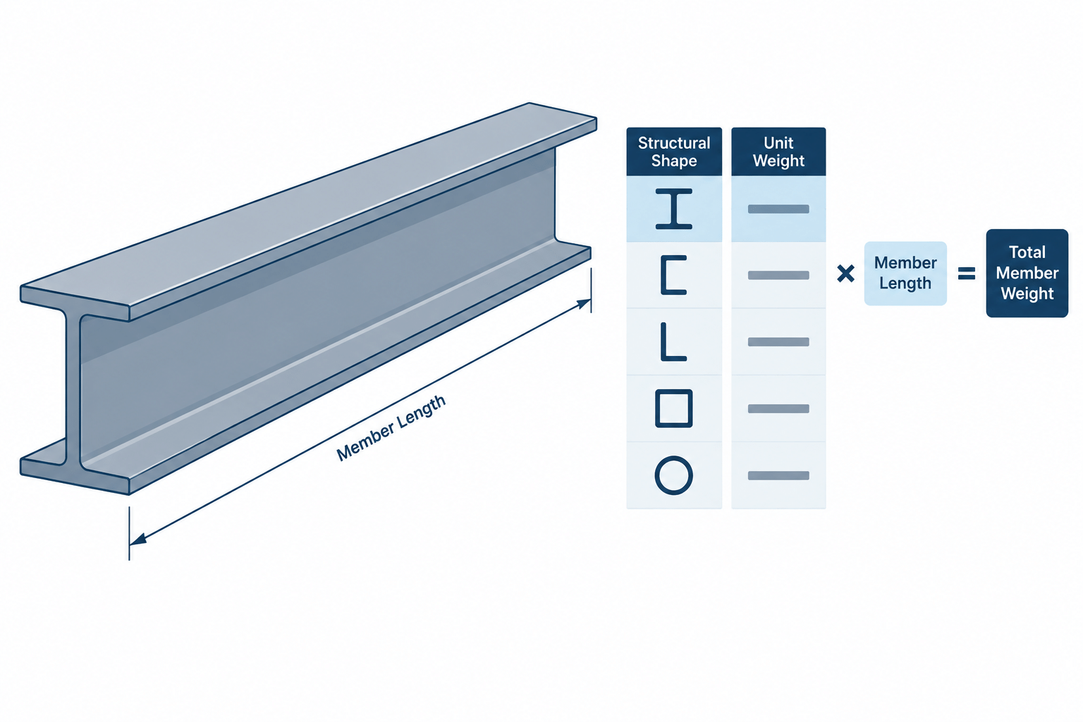
Calculating Structural Steel Member Weight from Shape Tables
Learn how to calculate structural steel member weight from published unit weight and member length, with practical guidance for takeoffs, CAD models, plates, holes, and assemblies.
Written by
-
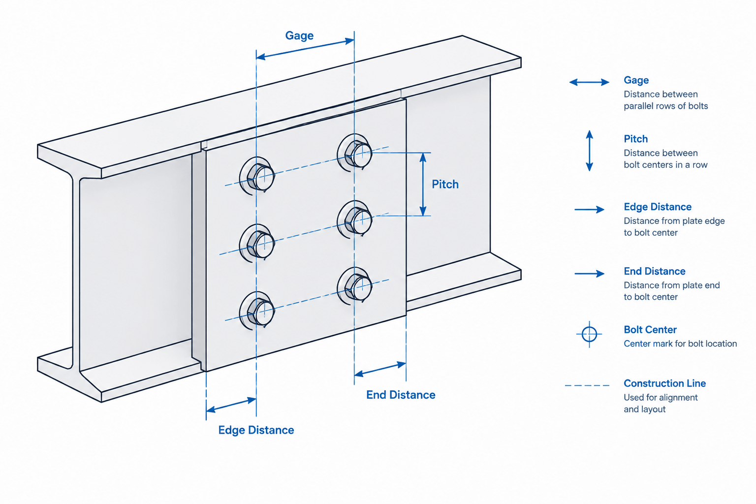
Bolt Layout Terminology in Steel Detailing: Gage, Pitch, Edge Distance, and End Distance
Learn how gage, pitch, edge distance, end distance, stagger, and hole spacing are interpreted in structural steel detailing and CAD drawings.
Written by
-
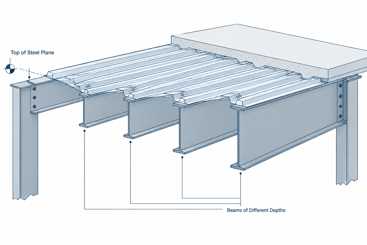
Top of Steel Elevations in Structural Drawings: TOS, BOS, Slopes, and Camber
Learn how top of steel elevations relate to beam depth, slope, camber, connections, and CAD coordination in structural steel drawings.
Written by
-
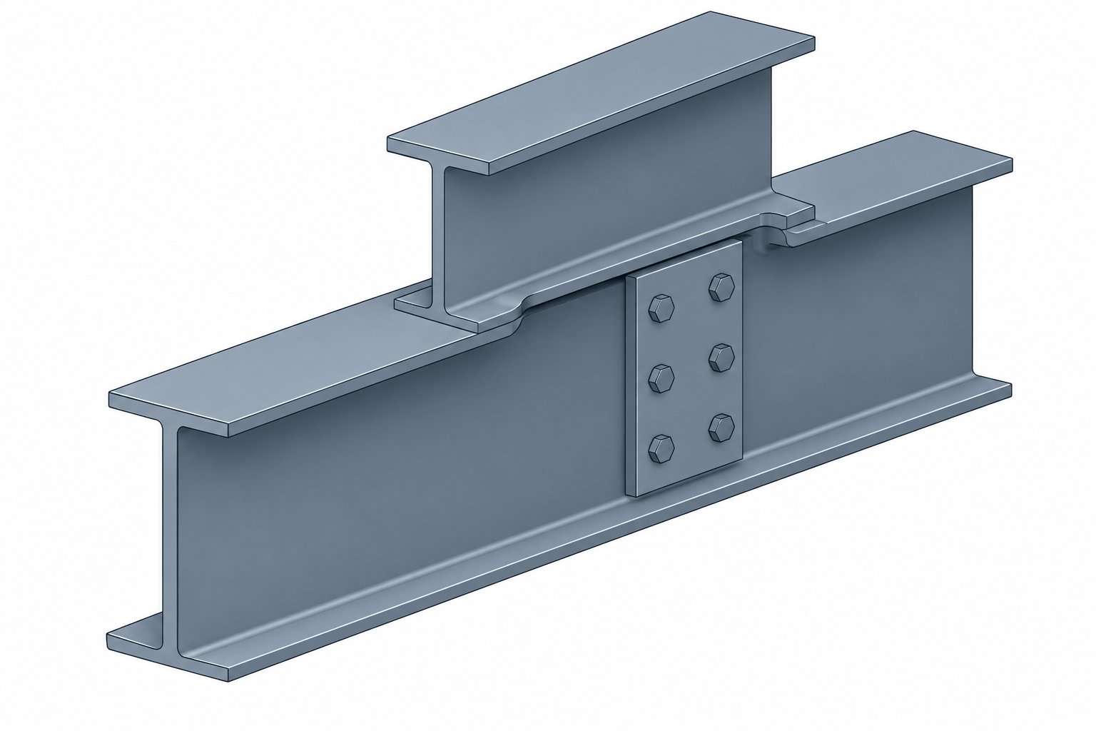
Beam Copes in Structural Steel Detailing: Geometry, Dimensions, and Drawing Practice
Learn how beam copes are represented and dimensioned in structural steel drawings, including top, bottom, and double copes, corner radii, clearances, and CAD checks.
Written by
-
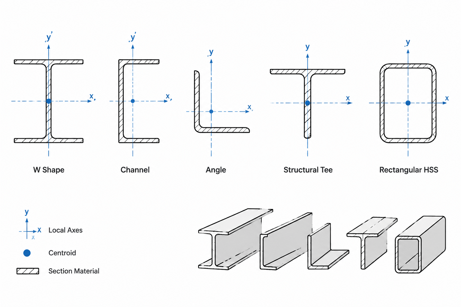
Centroid Coordinates in Steel Shape Tables: x̄, ȳ, Reference Axes, and CAD Placement
Learn how to interpret x-bar and y-bar centroid coordinates for W shapes, channels, angles, tees, and HSS, including reference origins and CAD checks.
Written by
-
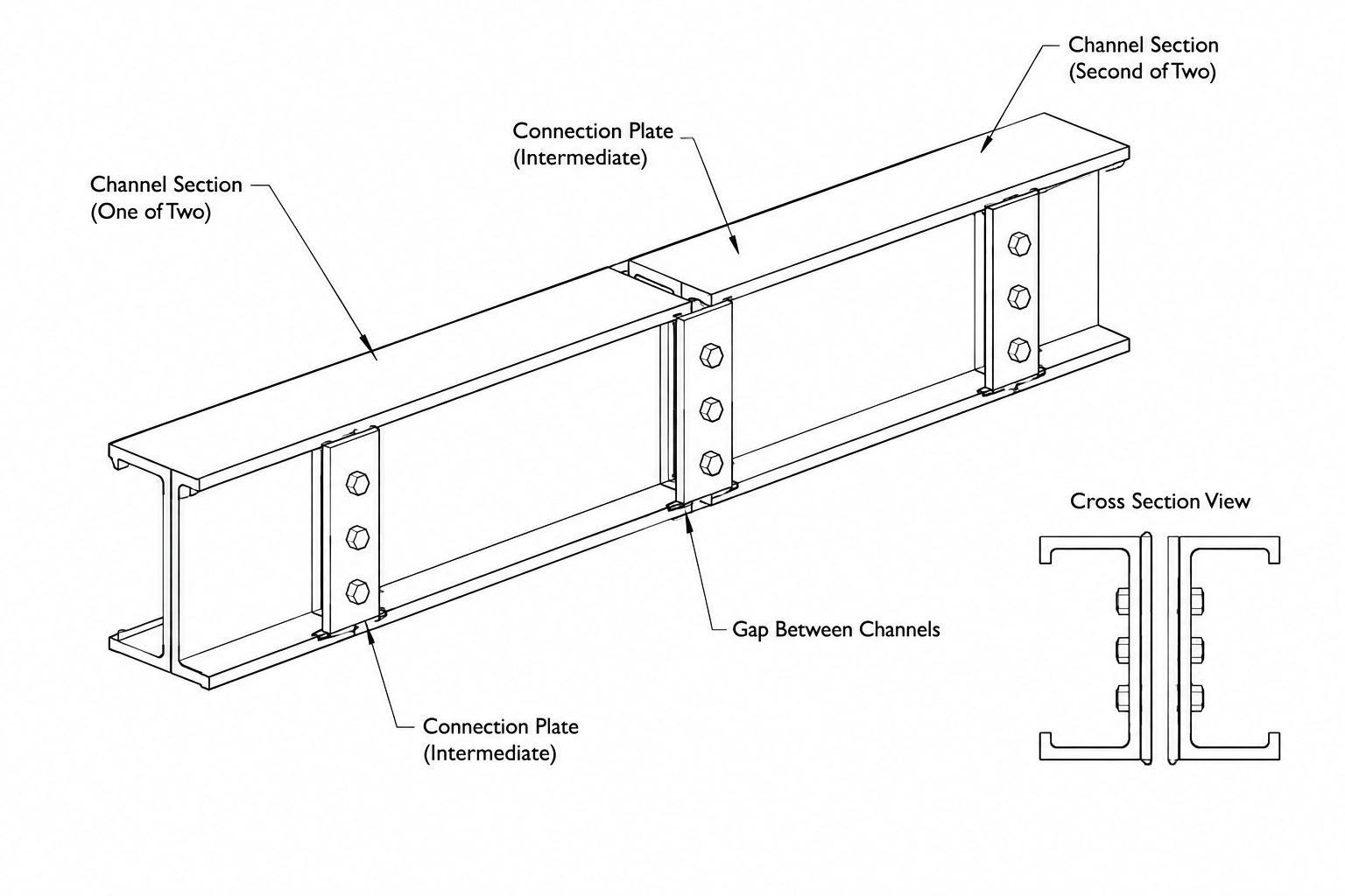
Back-to-Back Steel Channels and Angles: Orientation, Spacing, and Detailing
Learn how to detail back-to-back steel channels and angles, including orientation, spacing, built-up behavior, section properties, and CAD drawing practice.
Written by
-
Flange and Web Thickness in Steel Shape Tables: Understanding tf and tw
Learn how to interpret flange thickness tf and web thickness tw in steel shape tables and apply them correctly in CAD, detailing, and connection layouts.
Written by