Author: draftsman
-
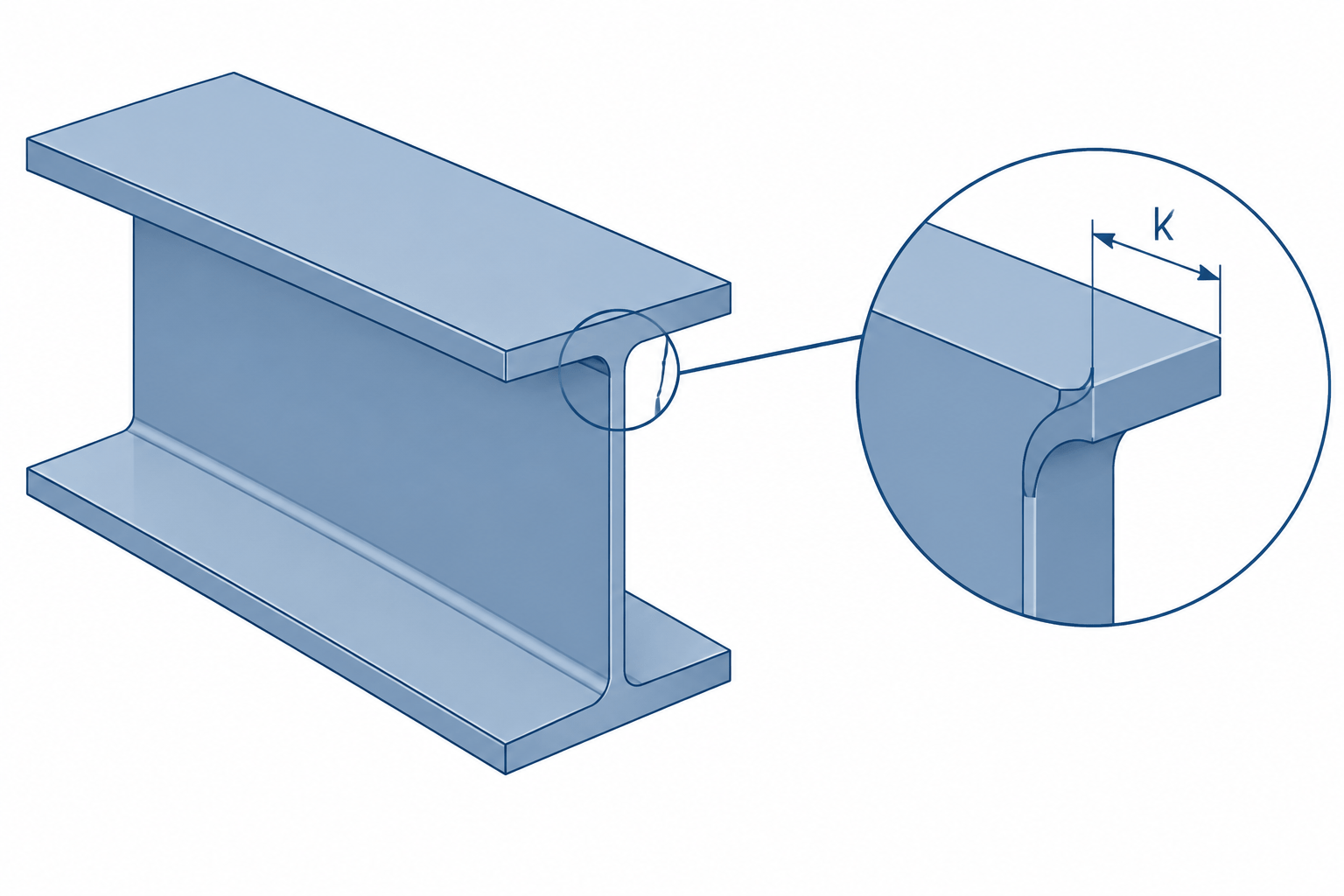
Steel Shape k Dimensions: Rolled Fillets, Detailing Clearance, and CAD Geometry
Learn what the steel shape k dimension represents and how rolled fillets affect connection detailing, clearances, stiffeners, and CAD outlines.
Written by
-
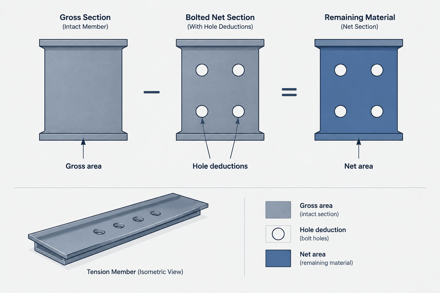
Gross Area vs. Net Area in Structural Steel Members
Learn how gross, net, and effective net area differ in steel members, why shape tables list gross area, and how holes and connection geometry affect calculations.
Written by
-
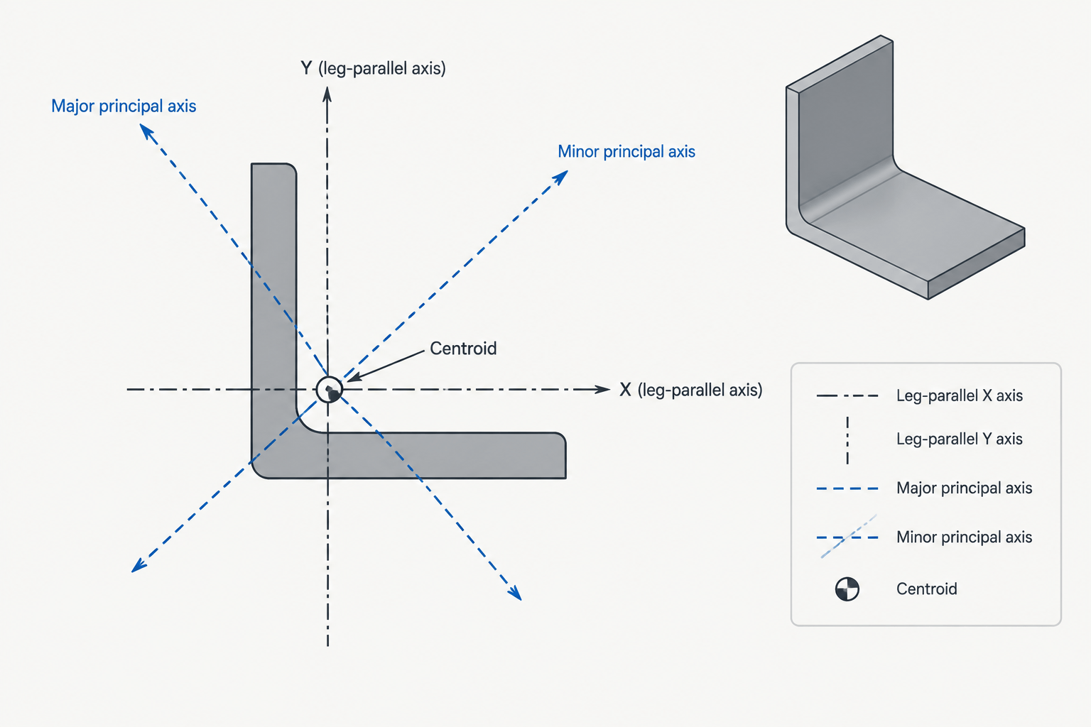
Principal Axes of Steel Angles: How to Read and Use Rotated Section Properties
Learn why steel angles have rotated principal axes, how principal properties differ from x-y values, and how to represent them correctly in CAD.
Written by
-
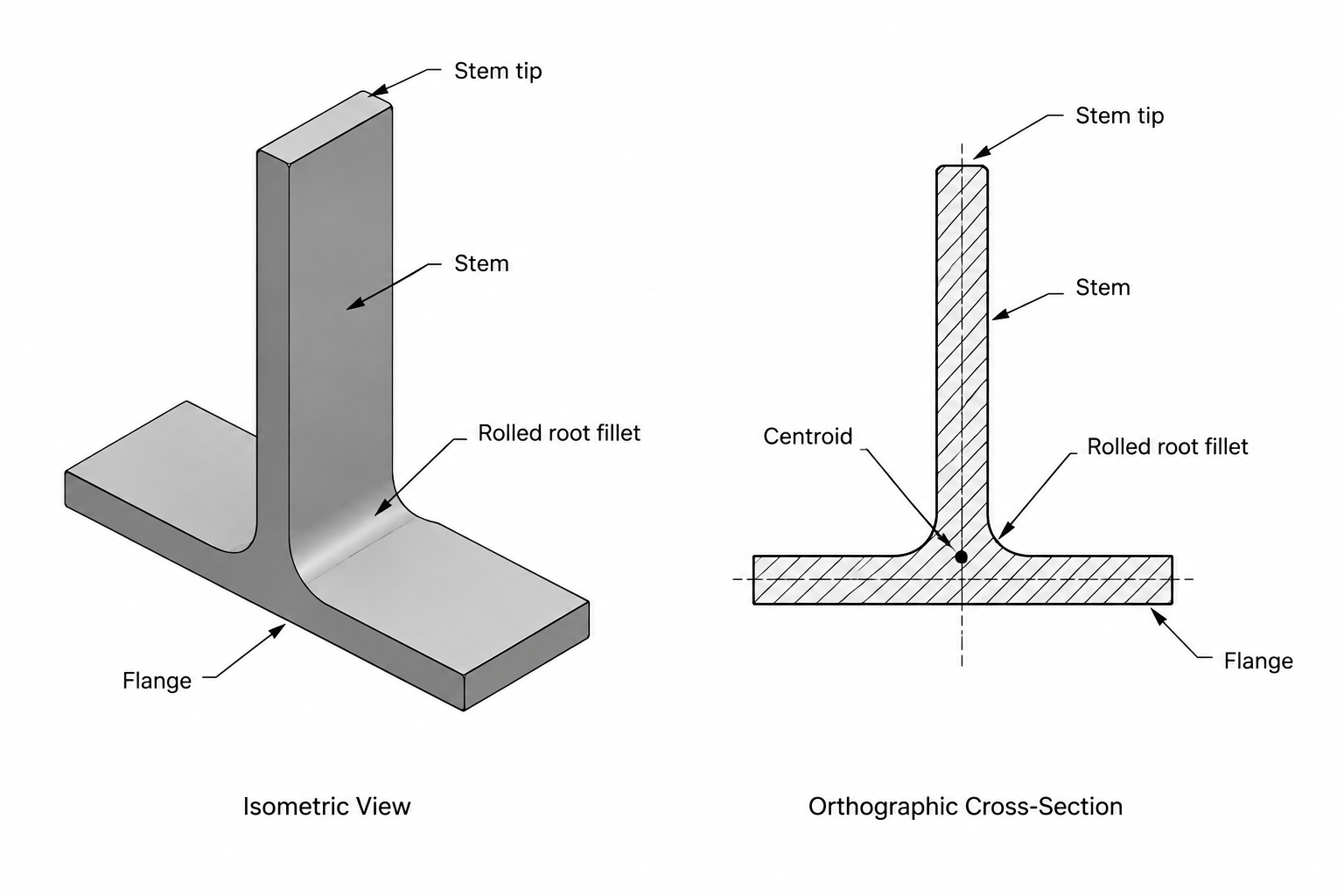
Structural Tee (WT) Shapes: Designations, Orientation, and Detailing Geometry
Learn how structural tee WT shapes are designated, oriented, detailed, and modeled, including centroid location, cut edges, fillets, and connection geometry.
Written by
-
Elastic vs. Plastic Section Modulus: S and Z in Steel Shape Tables
Learn the difference between elastic section modulus S and plastic section modulus Z, how each relates to steel shape geometry, and how to read them in section tables.
Written by

-
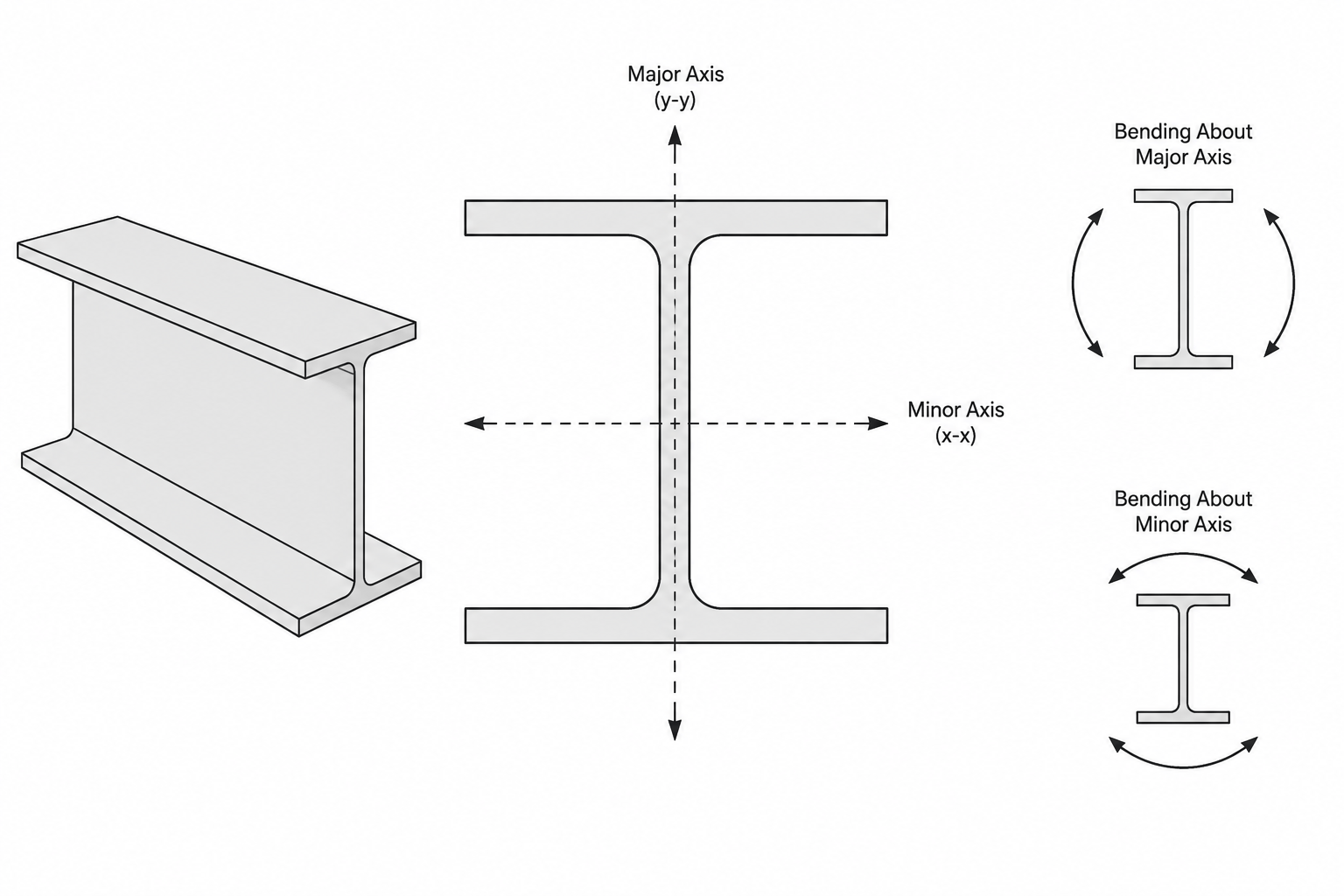
Strong Axis vs. Weak Axis in Structural Steel Sections
Learn how strong-axis and weak-axis bending relate to Ix, Iy, Sx, Sy, orientation, and detailing for W-shapes, channels, angles, tees, and HSS.
Written by
-
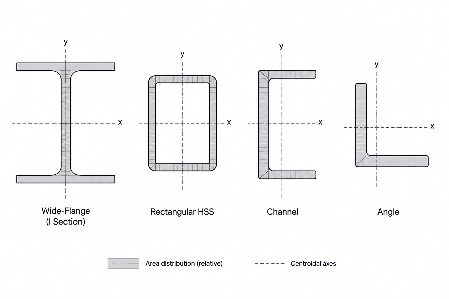
Radius of Gyration in Steel Shape Tables: Understanding rx, ry, and Slenderness
Learn what rx and ry mean in structural steel shape tables, how radius of gyration relates to moment of inertia, and why it matters in column slenderness.
Written by
-
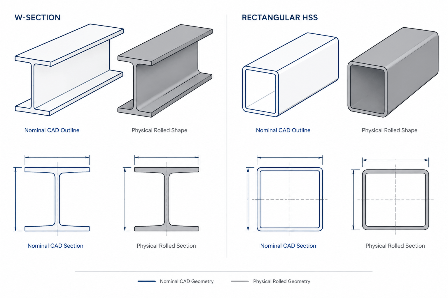
Nominal vs. Actual Structural Steel Dimensions: A Guide for CAD and Detailing
Learn how nominal steel dimensions, mill tolerances, fillets, HSS corners, and field conditions affect structural detailing and CAD geometry.
Written by
-
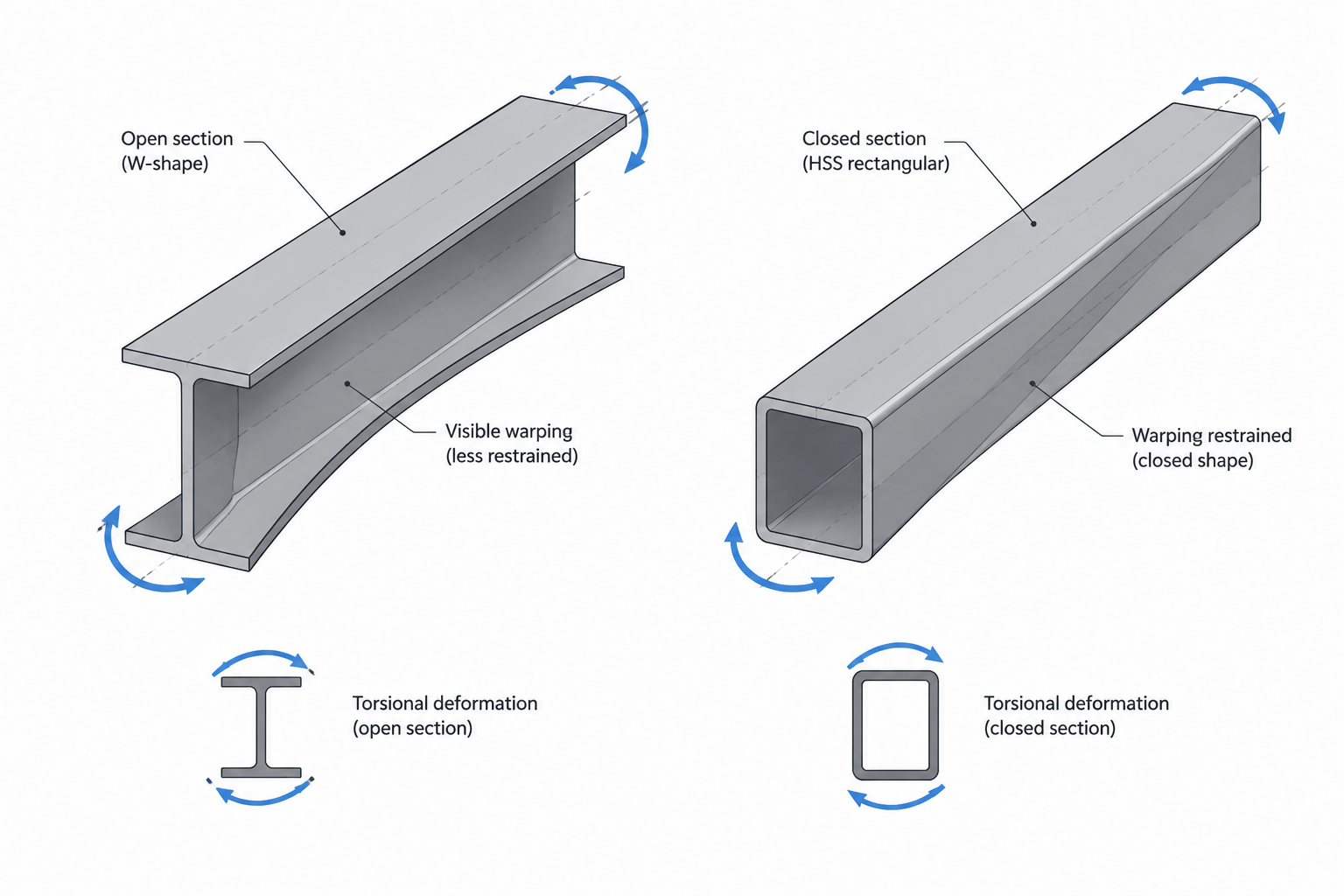
Torsional Constant J and Warping Constant Cw in Steel Shape Tables
Learn what J and Cw mean in structural steel shape tables, how open and closed sections resist torsion, and how to use these properties in design and CAD workflows.
Written by
-
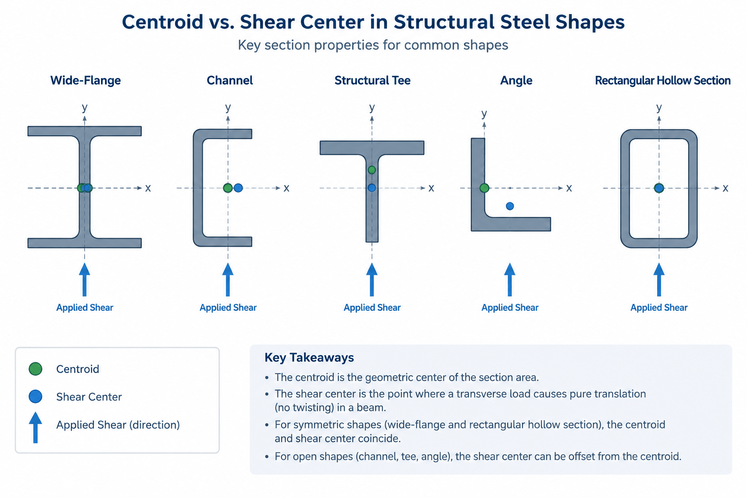
Shear Center vs. Centroid in Structural Steel Shapes
Learn how the shear center differs from the centroid in W-shapes, channels, tees, angles, and HSS, with practical detailing and CAD guidance.
Written by
-
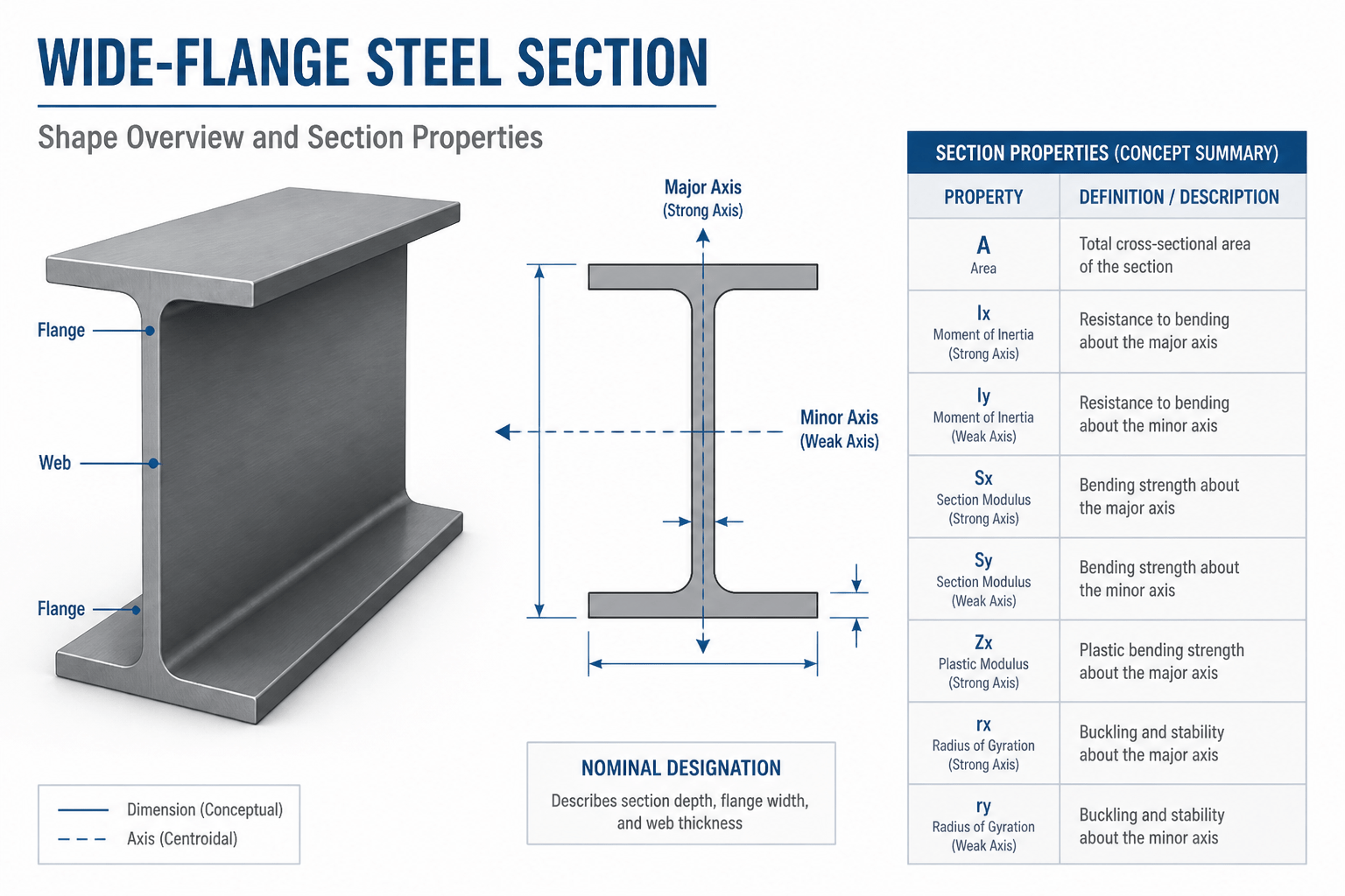
How to Read a W-Shape Steel Section Table
Learn how W-shape steel designations work and how to interpret depth, weight, axes, section properties, and CAD reference data.
Written by
-
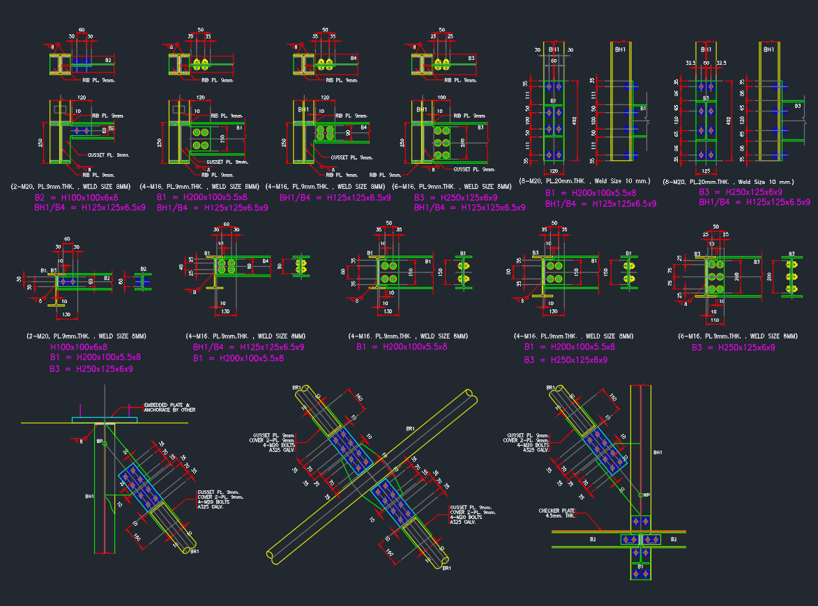
Structure Bolted Connection | AutoCAD Steel Drawing
The Structure Bolted Connection AutoCAD Drawing provides detailed layouts of bolted joints used in steel structure fabrication and assembly. This DWG file includes connection types such as beam-to-column, flange plate, and splice joints with bolt size, hole spacing, and plate thickness details. It is an essential reference for structural engineers, steel fabricators, and contractors to…
Written by