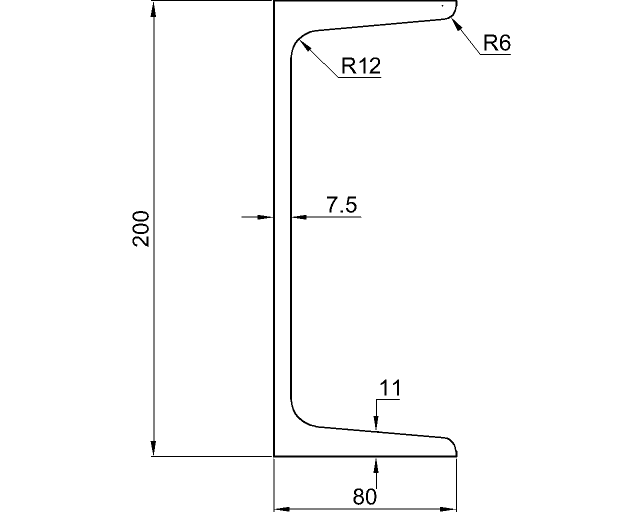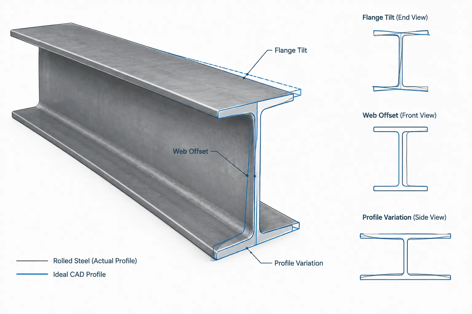
Steel shape tables provide dependable reference dimensions for design, estimating, drafting, and model coordination. A fabricated member, however, is a real rolled product rather than a mathematically perfect extrusion of the table profile. Its measured depth, flange width, web position, thickness, straightness, and angularity may differ slightly from the published values while still complying with the applicable product requirements.
This distinction matters whenever a detail depends on close contact or limited clearance. Plates fitted between flanges, inserts placed inside HSS, attachments near rolled fillets, and connections involving several aligned parts can all be sensitive to as-rolled steel shape variation. Good detailing does not require drawing every possible variation. It requires identifying which interfaces are sensitive, using the correct reference geometry, and providing an appropriate method for accommodating actual material.
What tabulated shape dimensions represent
Dimensions in a verified steel shape database describe the recognized section used for calculations and general detailing. They establish properties such as overall depth, flange width, web thickness, flange thickness, area, and axis locations. These values are the proper starting point for a CAD profile or structural model.
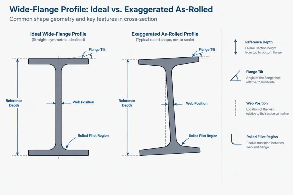
They should not be interpreted as a guarantee that every point on every delivered member will match the digital profile exactly. Rolling, straightening, cooling, cutting, and handling introduce permitted variation. Some dimensions may also be represented in tables using conventions suited to engineering calculations rather than shop measurement at a particular point.
This leads to two related but different descriptions:
- Reference section geometry: the published profile used to identify, calculate, and normally model the shape.
- As-rolled geometry: the measurable geometry of a particular physical member, including permitted production variation.
Neither description makes the other invalid. Problems arise when a reference model is treated as an exact scan of material that has not yet been produced or measured.
Which geometric characteristics may vary?
The relevant characteristics depend on the shape family. The applicable material and product documents should be consulted when acceptance limits are needed; a general CAD profile is not a substitute for those requirements.
| Shape or feature | Potential variation affecting detailing | Typical fit concern |
|---|---|---|
| W, S, HP, and similar sections | Depth, flange width, flange tilt, web position, local out-of-square condition, and straightness | Fitted stiffeners, flange attachments, web-centered plates, and member alignment |
| Channels | Flange orientation, web flatness, depth, width, and straightness | Back-to-back spacing, toe clearance, and attachment alignment |
| Angles | Leg dimensions, leg angularity, thickness, and straightness | Contact against plates, outstanding-leg position, and bolt-line clearance |
| Round, square, or rectangular HSS | Outside dimensions, wall condition, corner shape, twist, and straightness | Internal inserts, wraparound plates, caps, collars, and adjacent finishes |
| Structural tees | Parent-shape variation combined with effects associated with splitting and straightening | Stem alignment, flange flatness, and paired or repeated assemblies |
Thickness variation is only one part of the issue. A web can remain within acceptable product geometry yet not sit exactly where an idealized model places it. Similarly, two flange tips may not define perfectly parallel planes. For many ordinary connections these differences are inconsequential. For a tightly fitted component, they may control whether the part seats properly.
Do not confuse section variation with member deformation
Several geometric conditions are often grouped together even though they describe different things:
- Section dimensional variation concerns the cross-sectional shape, such as depth or flange width.
- Sweep is lateral deviation along the member length.
- Camber is curvature in the plane typically associated with member depth, whether specified or incidental.
- Twist is rotation of the cross section along the member.
- Fabrication distortion may result from cutting, welding, heat input, or handling after rolling.
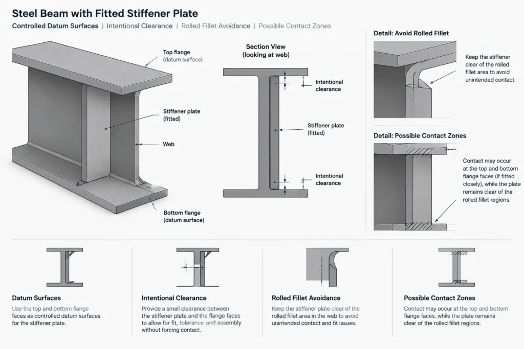
A connection can be affected by more than one condition at once. For example, a plate spanning between beam flanges may be sensitive to section depth and flange tilt, while its alignment with another member may also be influenced by sweep or twist. The drawing should address the functional interface rather than assuming that one generic tolerance note resolves every condition.
Where exact-profile CAD models can mislead
A clean CAD block normally represents a consistent section swept along a straight path. That is appropriate for most layout, interference detection, material takeoff, and drawing production. It becomes misleading when users infer fabrication precision from the visual contact between ideal solids.
Plates fitted between flanges
A stiffener or connection plate modeled to touch both flange surfaces may have no allowance for actual depth, flange tilt, or rolled fillets. The detail must clarify which edges require bearing or fitting, which may have clearance, and whether trimming or fitting is expected. A visually perfect CAD contact does not communicate those decisions.
Components fitted inside HSS
An internal diaphragm, sleeve, splice element, or insert cannot be sized safely from a nominal clear opening alone. Wall variation, corner geometry, weld seam location, and local distortion may reduce usable space. When the internal fit is critical, the solution may require clearance, a fabrication procedure, or measurement of the actual section.
Attachments wrapping around shapes
Collars, bent plates, saddles, and close-fitting brackets interact with several surfaces at once. Small changes in width, depth, corner shape, or angularity can prevent simultaneous contact. Details should avoid overconstraining the part unless field or shop fitting is intentionally part of the plan.
Repeated assemblies
A prototype detail that fits one member is not automatically interchangeable across every piece of the same designation. Repetition increases the importance of defining clearance, inspection, and adjustment strategies rather than relying on a single ideal profile.
A practical CAD and detailing workflow
1. Start with verified reference data
Create the base shape from a reliable table or verified SteelSTD.com profile. Confirm the shape family, designation, units, axis orientation, and source. Do not alter the standard profile merely to imitate an assumed rolling condition.
2. Identify fit-critical interfaces
Review the assembly for parts that contact multiple rolled surfaces, enter closed sections, pass close to fillets, or depend on small gaps. These locations deserve more attention than ordinary open clearances.
3. Separate member datums from variable surfaces
Dimension the assembly from intentional work lines, centerlines, grid lines, faces, or connection planes. Avoid creating a chain of dimensions in which every hole and plate location depends on an opposite flange tip or another surface that may vary.
4. Define the functional condition
Determine whether the interface requires bearing, welding access, free movement, architectural alignment, insertion clearance, or simply clash avoidance. Different functions call for different detailing responses. An arbitrary gap is not a substitute for understanding the load path and fabrication sequence.
5. Show allowances outside the master shape profile
Clearance envelopes, keep-out regions, and fit allowances can be represented with separate construction geometry, parameters, notes, or checking objects. This preserves the integrity of the reference section while making uncertainty visible during coordination.
6. Escalate details that require actual measurements
If satisfactory fit depends on the exact dimensions of a particular member, the workflow may need shop verification, a template, match marking, or fabrication from measured material. The responsible project team should define that process. A generic database profile cannot provide member-specific measurements.
Should the CAD profile include mill tolerances?
Usually, a reusable shape block should remain based on the published reference dimensions. Creating a randomly oversized or undersized section does not represent a controlled worst case and may introduce new errors into weight calculations, connection locations, and drawing dimensions.
For clearance studies, it can be useful to create separate limit envelopes based on verified project criteria and applicable product requirements. These should be clearly distinguished from the nominal model. A good model may therefore contain three conceptual layers:
- the reference steel profile;
- the required connection or attachment geometry; and
- a coordination envelope representing relevant variation or clearance.
This approach is more informative than silently changing the steel block because reviewers can see what is published geometry and what is an allowance.
Drawing notes are not a substitute for workable geometry
Broad notes such as “field verify” or “fit as required” may identify uncertainty, but they do not automatically create a fabricable detail. The drawing should still communicate the controlling datum, intended contact, installation sequence, and responsibility for adjustment. Verification notes are most useful when they identify what must be measured and how that measurement affects fabrication.
Likewise, specifying unusually tight alignment without considering ordinary product and fabrication variation can transfer an unresolved geometry problem to the shop or field. Fit requirements should be coordinated with the engineer, fabricator, erector, and other affected trades as appropriate.
Key takeaway
Steel shape tables and CAD profiles provide the correct reference geometry, but they do not describe every local feature of every delivered member. As-rolled steel shape variation becomes important where components are trapped between surfaces, inserted into closed sections, wrapped around profiles, or aligned across several members.
Keep the master model tied to verified published data. Then address fit through clear datums, purposeful clearances, separate coordination envelopes, and actual-member verification when necessary. This preserves the usefulness of standardized shape data while recognizing the realities of rolling, fabrication, and erection.