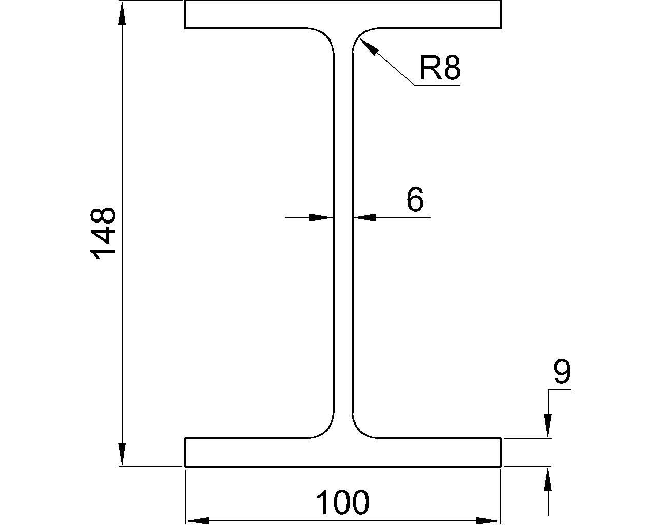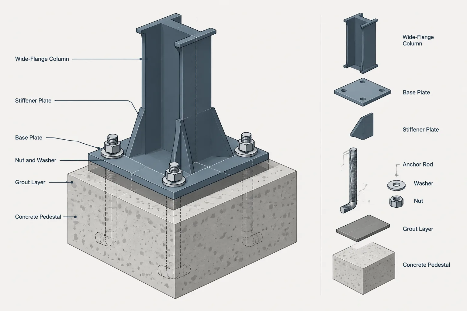
An anchor rod template and base plate hole layout describe related geometry, but they are not interchangeable drawings. The template positions rods during concrete placement, while the base plate must fit over the installed rods and transfer forces between the steel column and foundation. Small differences in reference points, rotation, hole assumptions, or elevation can create costly field conflicts.
Reliable detailing begins by establishing one coordinated layout from the structural design documents. That layout must remain consistent across foundation plans, concrete drawings, setting plans, shop drawings, erection drawings, and fabrication files. This guide explains the information that should be coordinated without prescribing project-specific dimensions or tolerances.
Anchor Rods, Base Plate Holes, and Templates
An anchor rod is a steel anchorage component embedded in or connected to the concrete foundation. Some drawings and specifications use the term anchor bolt, but the detailer should follow the terminology used in the project documents.
A base plate hole is the opening through which an anchor rod passes. Its size and shape may reflect erection clearance, the anchorage design, washer requirements, and the applicable project criteria. Base plate anchor holes should not automatically be treated like holes in a conventional bolted steel-to-steel connection.
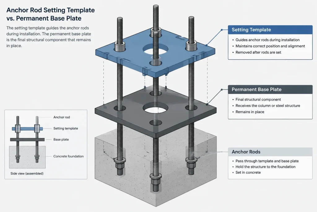
An anchor rod template is a layout device used to hold rods in their intended horizontal positions during placement. A template may also help control projection and orientation, depending on the installation method. It is generally a construction aid rather than a substitute for the permanent base plate.
Start with the Governing Reference Geometry
Every anchor rod group needs an unambiguous relationship to the building grid and the supported steel member. The layout should not depend only on dimensions chained from an edge of concrete, because foundation edges can change while the structural grid remains the controlling reference.
A coordinated layout commonly identifies:
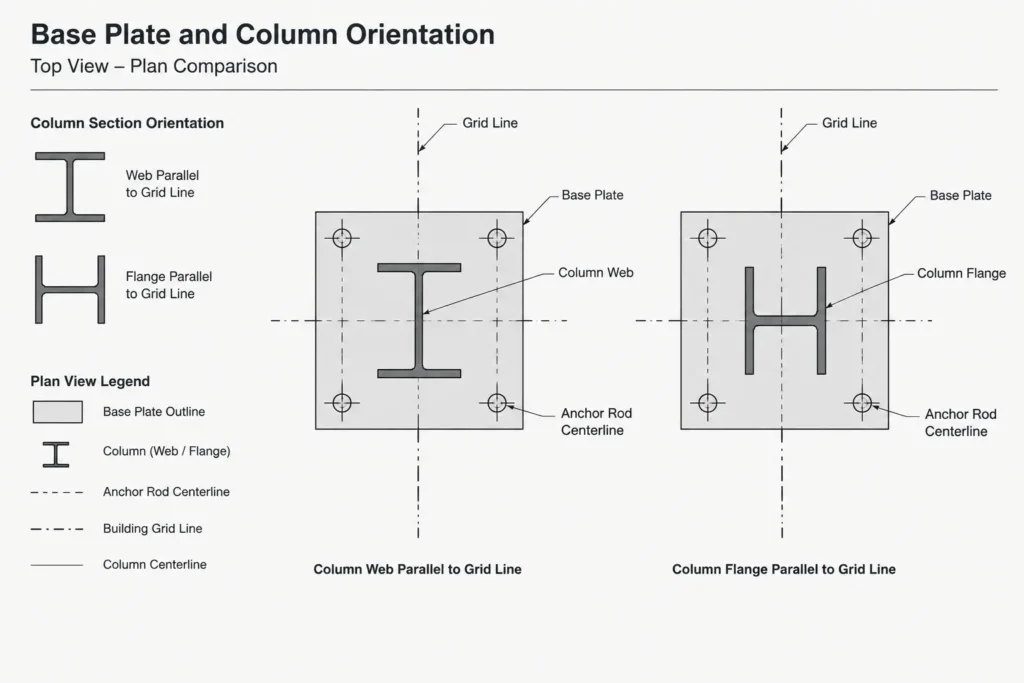
- Building grid lines or other established control lines
- The column work point or intended member centerline intersection
- Base plate centerlines and orientation
- Anchor rod center-to-center dimensions in both plan directions
- Any offset between the column, base plate, rod group, and concrete support
- The direction of the column web, flanges, or HSS faces
- The top elevation of the concrete support or grout interface
- The required rod projection relative to the controlling elevation
Do not assume that the column centroid, base plate center, rod-group center, and concrete pedestal center always coincide. Eccentric layouts may be intentional because of architectural constraints, foundation geometry, edge distances, or load-transfer requirements.
Use Stable Datums
Dimensions should originate from stable datums that can be used by both the concrete and steel trades. Grid intersections, surveyed control lines, and clearly defined top elevations are usually more dependable than unfinished concrete edges or visually estimated column locations.
If a detail uses local coordinates, the drawing should still show how those coordinates relate to the project grid. A correct local rod pattern can be installed in the wrong place if its origin or rotation is unclear.
Template Geometry Is Not Automatically Base Plate Geometry
A template drawing may resemble a base plate plan, but each serves a different purpose. The base plate is a permanent structural component. The template must hold the rods while allowing concrete placement, consolidation, access, and later removal or incorporation as specified.
| Item | Primary purpose | Key coordination question |
|---|---|---|
| Base plate | Transfers forces and provides the column-to-foundation interface | Do plate size, thickness, holes, welds, and column orientation match the design? |
| Anchor rod | Provides the specified anchorage to the foundation | Are location, projection, embedment arrangement, and hardware coordinated? |
| Setting template | Maintains the rod pattern during installation | Can it control spacing and rotation without obstructing placement? |
| Washer or plate washer | Distributes force around the base plate opening as designed | Does it fit the hole, rod, nut, plate edge, column, and weld geometry? |
| Leveling component | Supports or adjusts the plate before final bearing is established | Is there sufficient access and compatible elevation control? |
The template hole size may differ from the base plate hole size because the template has a different function. Neither dimension should be inferred from the other unless the project documents explicitly establish that relationship.
Rod Projection and Elevation Coordination
Plan location is only half of the problem. An anchor rod can be correctly positioned in plan and still be unusable because its projection is too short, excessively long, or inconsistent with the intended leveling and grouting arrangement.
Projection coordination should account for the full vertical assembly, including:
- The controlling concrete or grout elevation
- The base plate thickness
- Any leveling nut, leveling plate, shim, or other approved support method
- The washer or plate washer
- The nut and required thread engagement
- Any exposed-thread limitations or protective requirements
Detailers should distinguish between the top of concrete, top of grout, bottom of base plate, and top of base plate. These elevations may not be identical. A note such as “rod projection above concrete” is incomplete if the referenced concrete elevation is not clearly defined.
Hole Clearance Is a Design and Constructability Issue
Base plate holes often include installation clearance, but larger openings affect washer selection, plate behavior, edge clearance, and force transfer. The detailer should therefore use the hole size and washer arrangement established by the design documents rather than enlarging holes solely for convenience.
Questions to resolve before fabrication include:
- Are the holes round, slotted, or otherwise detailed?
- What rod diameter and hardware apply?
- Are special washers or plate washers required?
- Will washers interfere with the column, stiffeners, welds, or plate edges?
- Does the rod group permit the intended erection adjustment?
- Are field modifications prohibited or subject to engineering review?
Slots also require a clearly shown direction. A slotted opening drawn without an orientation dimension can be interpreted differently after a view is rotated or mirrored.
Column Orientation and Pattern Symmetry
A symmetric rod group can conceal a column-orientation error. For example, the base plate may fit over the rods after a quarter-turn even though the column web and flanges face the wrong directions. Conversely, an asymmetric rod group may make a mirrored or rotated plate impossible to erect.
Plans should show an orientation feature that survives through the workflow, such as:
- Column web direction
- Major and minor member axes
- A labeled plate edge
- An offset rod or asymmetric dimension
- A match mark coordinated with the setting plan
North arrows alone are not always sufficient, particularly when details are shown in local views or when similar column types occur on multiple grid lines.
A Practical CAD and Detailing Workflow
1. Build One Controlled Layout
Create the rod pattern from verified dimensions and place it relative to the column work point. Avoid independently redrawing the pattern for the template, base plate, and erection plan. Reusing controlled geometry reduces transcription errors.
2. Separate Components by Layer or Object Type
Keep anchor rods, base plate edges, column outlines, concrete limits, centerlines, dimensions, and annotations visually distinct. This makes interference checks easier and prevents a template outline from being mistaken for the permanent plate.
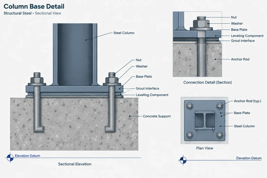
3. Check the Assembly, Not Just the Hole Centers
Overlay the column profile, weld limits, stiffeners, washers, nuts, and tool-access zones. A hole can be correctly located while the nut remains inaccessible or the washer intersects a weld.
4. Verify Rotation and Mirroring
Compare the shop view with the erection orientation and foundation plan. Confirm that export, block insertion, or view generation has not mirrored an asymmetric pattern.
5. Issue Consistent Information
The setting plan, template detail, and base plate shop detail should communicate the same rod coordinates and orientation. If different dimensioning schemes are necessary, perform an independent cross-check before release.
Field Verification and Nonconforming Rods
Installed anchor rods should be surveyed or otherwise verified before steel erection when required by the project workflow. Verification is especially valuable before fabrication is complete, because it may reveal pattern shifts, rotation, projection issues, or individual rods outside the intended position.
The field survey should use the same datums as the detailing model. A list of offsets is difficult to apply if it does not state the grid intersection, axis directions, elevation reference, and sign convention.
Field crews should not bend, cut, heat, weld, relocate, or otherwise modify anchor rods without the required engineering review and project authorization. Similarly, base plate holes should not be enlarged in the field merely because a rod does not fit. The effect on anchorage, washers, plate behavior, edge conditions, and erection stability must be evaluated.
Final Coordination Checklist
- Confirm the governing grid intersection and column work point.
- Verify column, plate, and rod-group offsets independently.
- Show column orientation in addition to the rod pattern.
- Coordinate base plate holes with rods, washers, nuts, welds, and stiffeners.
- Define the elevation from which rod projection is measured.
- Check the intended leveling and grouting sequence.
- Distinguish template holes from permanent base plate holes.
- Verify slot direction and any asymmetric features.
- Compare setting plans, concrete drawings, and steel shop drawings.
- Document field survey datums and resolve discrepancies before erection.
A successful anchor rod layout is not simply a pattern of circles. It is a coordinated three-dimensional interface between concrete construction, steel fabrication, and erection. Clear datums, controlled geometry, explicit orientation, and early field verification provide the best defense against base plate fit-up problems.