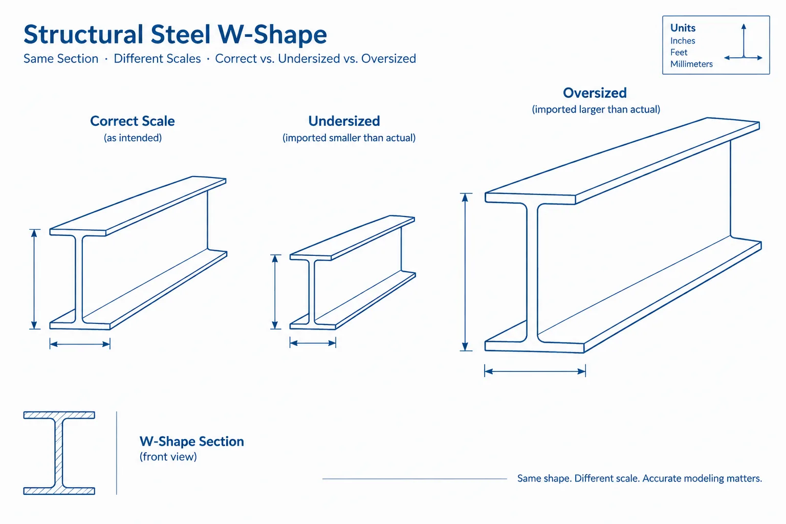
A structural steel CAD file can look correct on screen while being completely wrong in size. A W-shape outline may have the right proportions, an HSS section may appear square, and a base plate detail may fit neatly on a sheet—yet the geometry could be stored in inches, feet, millimeters, or an undocumented drawing-unit convention.
This problem is especially common when steel shape blocks, consultant backgrounds, survey files, fabrication details, and exported models are combined. Reliable coordination requires more than choosing an insertion scale that makes the drawing look reasonable. The receiving user must identify what one CAD unit represents, confirm that assumption against known geometry, and preserve the distinction between model size and plotted size.
Four Scale Concepts That Should Not Be Confused
The word scale can refer to several different things in a CAD workflow. Treating them as interchangeable is a common source of errors.
| Concept | What it controls | Typical question |
|---|---|---|
| Drawing units | The real-world meaning assigned to coordinate values | Does one model unit represent an inch, a foot, or a millimeter? |
| Insertion conversion | The size adjustment applied when content moves between unit systems | Will this imported block be converted to the host drawing’s units? |
| Model geometry scale | Whether the actual objects were drawn at real size or manually reduced | Is this beam outline full size in model space? |
| View or plot scale | How full-size model geometry is presented on a sheet | How much of the model appears within the drawing view? |
Good structural drafting practice generally keeps physical objects at their intended real-world size in model space. Sheet views then control presentation. Scaling a steel member merely to make it fit on a page damages its value as coordinated geometry.
Why CAD Geometry May Not Identify Its Own Units Reliably
CAD geometry is fundamentally based on coordinates. Depending on the file format, export process, and software settings, unit metadata may be present, missing, ignored, or interpreted differently during insertion. A line with a stored length has no visual feature that proves whether the value represents inches or millimeters.
Text is not dependable evidence either. A note may describe an imperial steel shape while the surrounding drawing uses another unit convention. Dimensions can also display converted values, include scale factors, or be overridden. File names such as “metric” or “imperial” are helpful labels, but they are not geometric verification.
For downloaded steel CAD content, the safest approach is to treat the source unit as an item that must be checked rather than assumed.
Why Steel Shape Blocks Are Particularly Sensitive
Structural steel sections have recognizable proportions, which can hide unit errors. A uniformly mis-scaled W-shape still looks like a W-shape. The web, flanges, and fillets all remain proportional to one another, so a visual review may not reveal the problem.
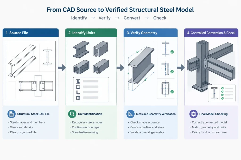
Incorrectly scaled shape geometry can affect:
- Member placement relative to grids and elevations
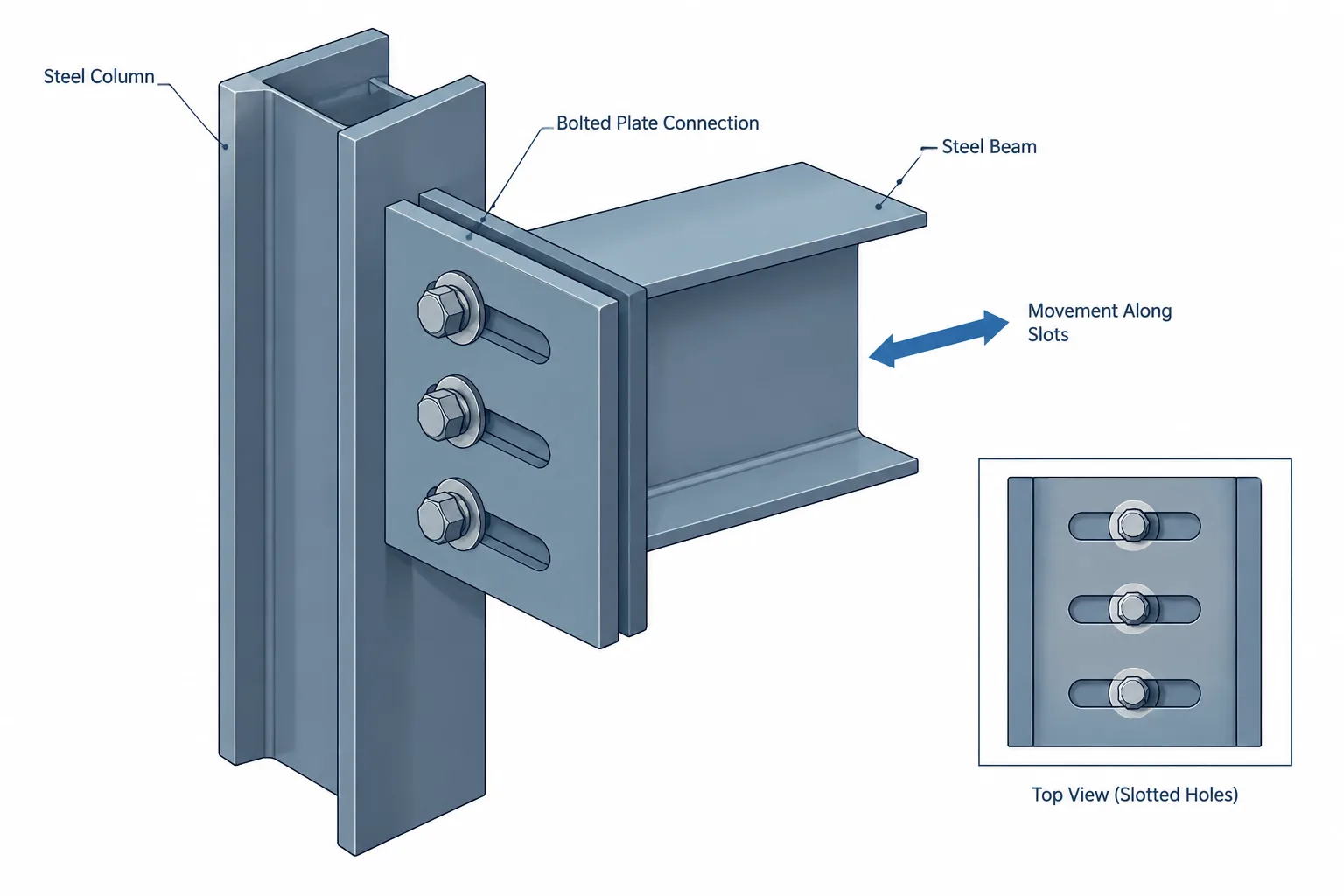
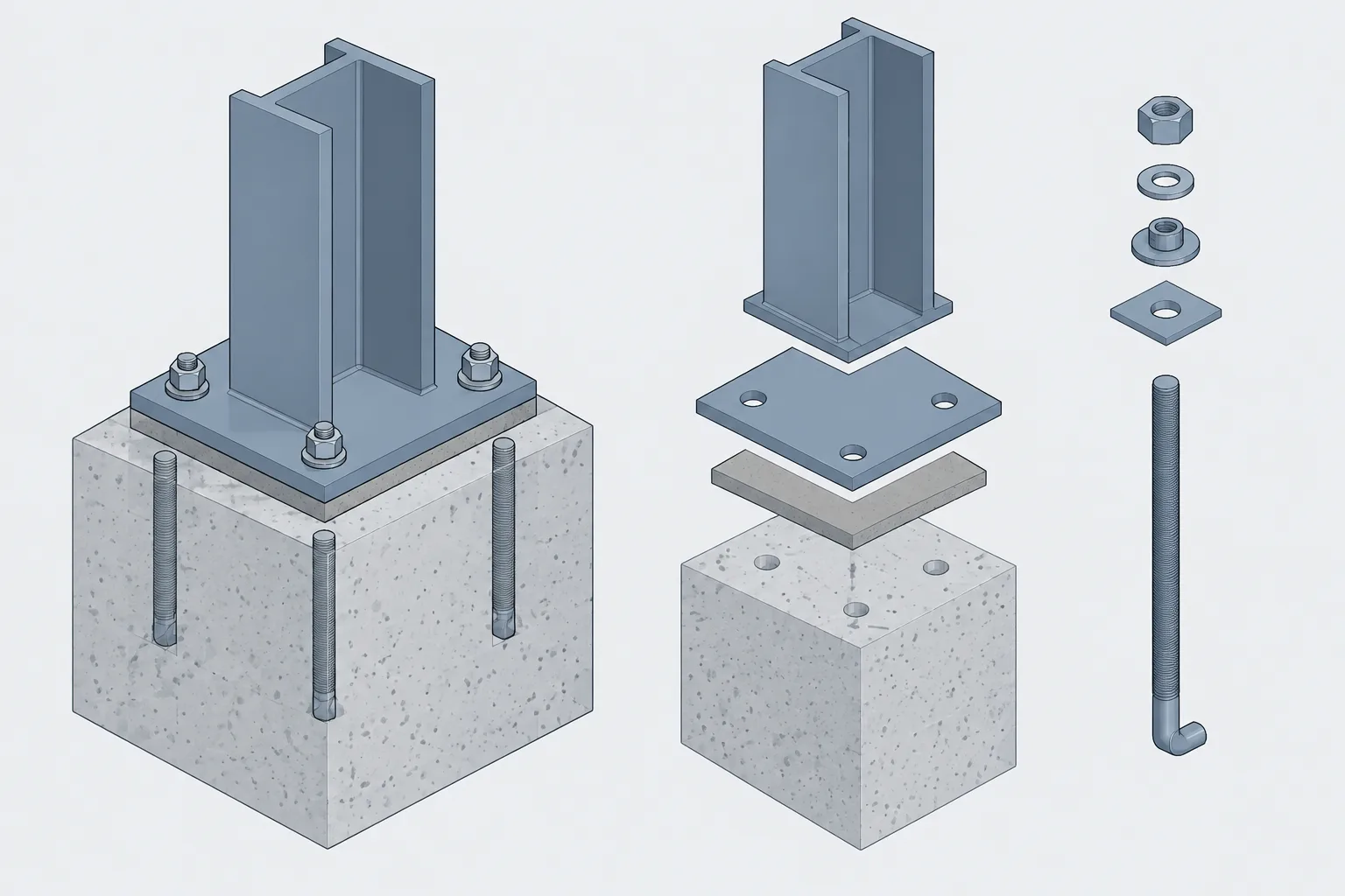
- Connection clearances at flanges, webs, and HSS faces
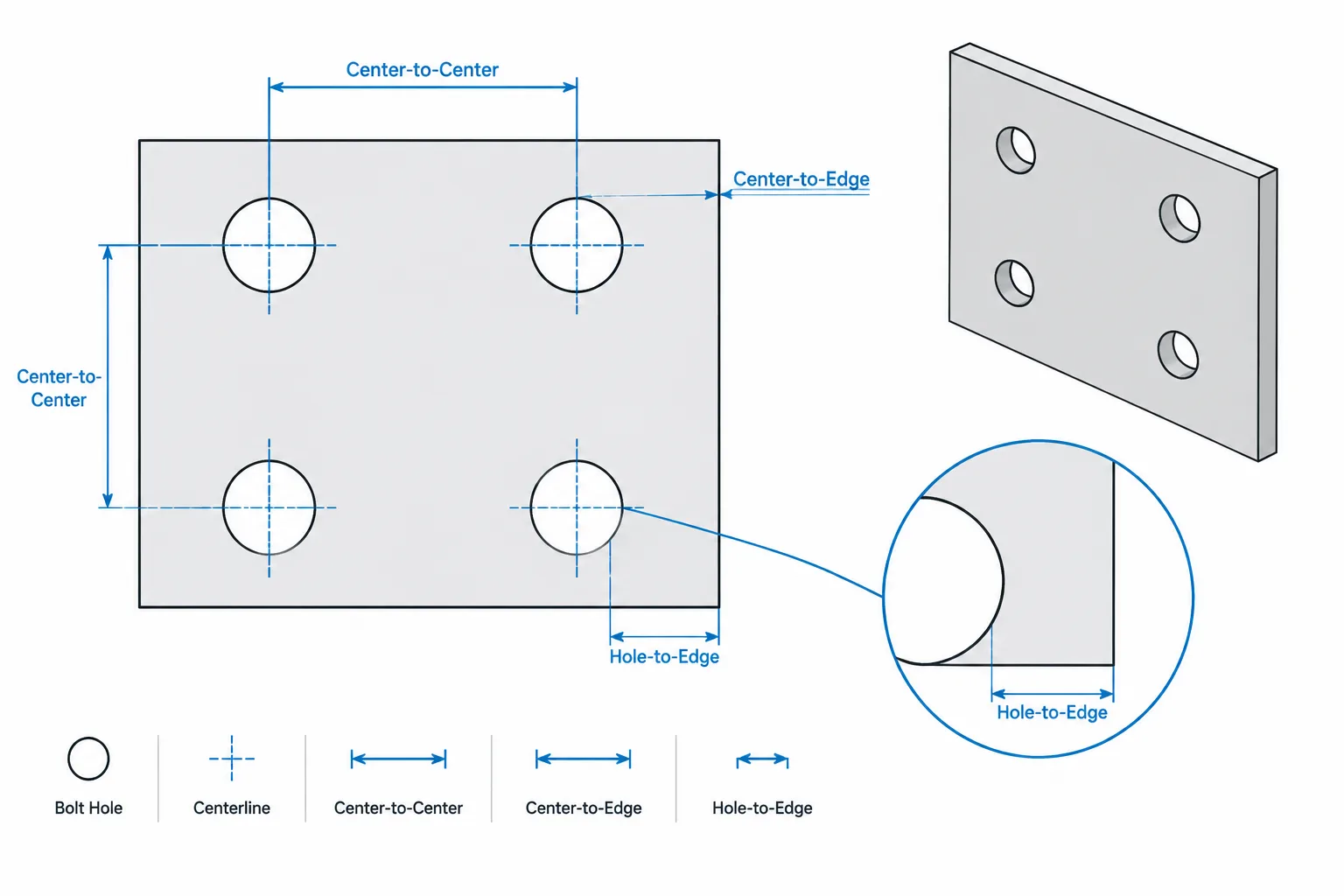
- Bolt-hole and plate layouts
- Cope, notch, slot, and end-cut geometry
- Clash detection with slabs, walls, equipment, and other members
- Quantity takeoffs based on object length, area, or volume
- Dimension values extracted directly from the model
- Section-property calculations performed from CAD outlines
A wrong insertion factor is not simply a display issue. Once the block is copied, exploded, trimmed, or used to create other parts, the unit error can spread through the project.
A Practical Verification Workflow
1. Inspect the source before insertion
Open the source file separately when possible. Review its drawing-unit settings, coordinate extents, notes, dimension styles, and any source documentation. This provides context without allowing questionable geometry to enter the project model.
Do not change units immediately. First determine whether the setting describes the existing geometry or merely establishes how future insertions should be interpreted. Changing a unit label does not necessarily resize objects already drawn.
2. Measure a recognizable object
Select an element with a known or independently verifiable size. For a steel shape, useful checks may include overall depth, flange width, wall dimension, plate thickness, or a documented member length. Compare the measured CAD distance with verified shape data or project information.
Use more than one dimension when practical. A single match may be coincidental, particularly in a mixed drawing containing schematic symbols or objects from several sources.
3. Determine the source and destination conventions
Establish two separate facts:
- What one unit represents in the source geometry
- What one unit represents in the destination model
The required conversion follows from that relationship. Avoid guessing from the apparent screen size, because zoom level has no connection to physical size.
4. Test with a temporary copy
Insert or reference the source into a controlled test file before adding it to the production model. Measure the resulting geometry and compare it against a known dimension. This reveals whether the software applied an automatic conversion, no conversion, or an unexpected setting inherited from one of the files.
5. Verify position as well as size
Correct size does not guarantee correct placement. Unit conversion can also affect insertion points, reference origins, grid coordinates, and elevation values. Confirm at least one known location after confirming object dimensions.
6. Record the decision
Document the identified source units, the destination convention, any conversion applied, and the dimension used for verification. A short import note can prevent another team member from applying the same conversion a second time.
Use Steel Shape Data as a Geometric Check
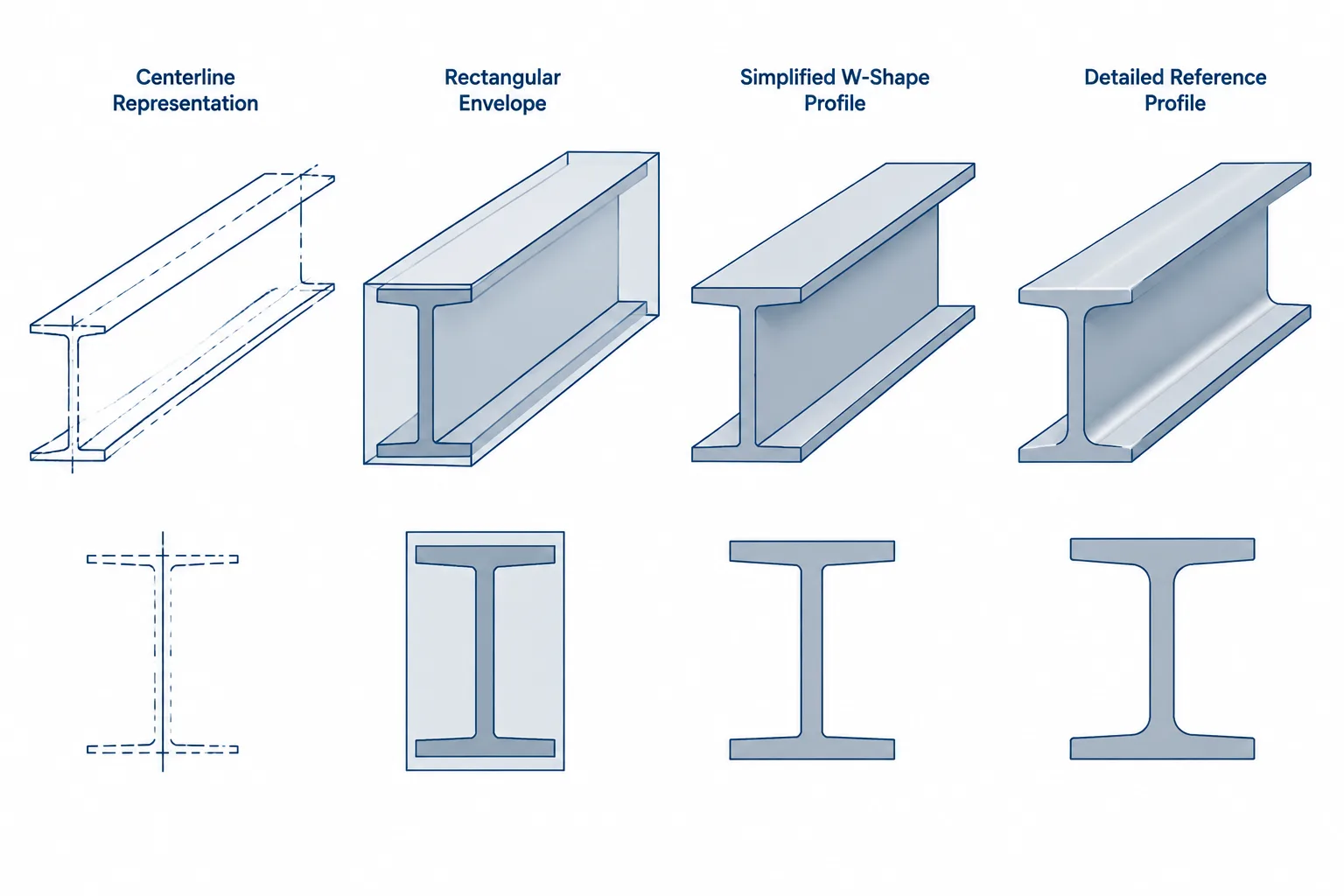
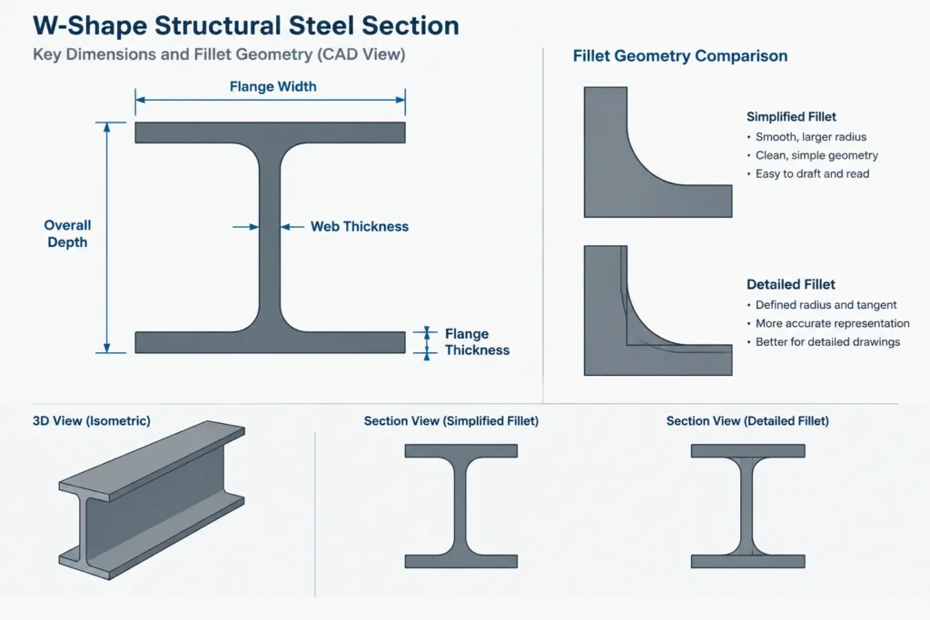
Verified structural shape information is useful for checking CAD blocks, but the comparison must use corresponding dimensions. An overall nominal designation is not always the same as the actual dimension represented by the outline. Rolled shapes may also contain fillets and surface geometry that simplified blocks omit.
For example, a simplified W-shape block may accurately represent overall depth, flange width, flange thickness, and web thickness while omitting rolled fillets. That does not automatically make the block incorrectly scaled. Conversely, matching the nominal name alone does not prove that its geometry is correct.
A sensible check is to compare several primary dimensions that are expected to appear in the selected representation. If section properties are calculated from the outline, also determine whether the drawing contains exact, simplified, or nominal geometry.
Common Failure Modes
Scaling until it looks right
Nearby columns, walls, or title-block graphics may also be wrong. Visual fit is not a substitute for measuring a verified object.
Trusting displayed dimensions without measuring
Dimension objects may contain conversion factors, alternate-unit displays, or manual text overrides. Measure the underlying geometry directly.
Changing the unit setting and assuming objects changed size
Unit declarations and object scaling are separate operations in many workflows. After changing any setting, remeasure the geometry.
Applying conversion twice
A user may manually scale a block even though the receiving software already converted it during insertion. The opposite problem occurs when both files are marked similarly even though their geometry was created under different conventions.
Scaling only part of an assembly
If geometry, hole centers, text, dimensions, and reference points are handled separately, the result may no longer represent a coordinated steel component. Keep related content together during conversion and verify it afterward.
Using plotted sheets to validate model geometry
Paper dimensions depend on view and plot settings. They do not directly establish the real size of model objects.
Mixed-Unit Project Coordination
A project can legitimately include design documents, vendor models, and fabrication information created under different unit systems. The goal is not to force every source file into the same authoring convention. The goal is to make each source predictable when it enters the coordination environment.
A simple CAD intake record can identify:
- Source organization or discipline
- File purpose and issue status
- Declared unit system
- Measured unit interpretation
- Reference origin and elevation basis
- Conversion method used
- Known dimension checked after import
When an external reference is expected to be updated, preserving it as a separate source may be safer than permanently scaling and editing a copy. Any transformation should be controlled so later revisions follow the same process.
Checklist Before Using a Steel CAD Resource
- Open the source independently and inspect its settings.
- Identify what one model unit represents.
- Measure at least one verified physical dimension.
- Prefer multiple checks on recognizable steel geometry.
- Confirm whether the block is exact, simplified, or schematic.
- Test insertion in a temporary file.
- Verify that automatic and manual conversions were not both applied.
- Check insertion point, coordinates, orientation, and elevation.
- Remeasure after insertion, reference attachment, or export.
- Document the accepted unit convention for other users.
Units Are a Model-Control Issue
Structural steel CAD units affect far more than drawing appearance. They influence geometry, connection fit, coordinate exchange, quantity extraction, and every dimension derived from the model. A reliable workflow separates drawing units from view scale, validates imported content against known steel dimensions, and records how each external file was interpreted.
Before using any downloaded shape block or consultant model as a basis for detailing, confirm both its dimensional accuracy and its unit convention. The few minutes spent measuring a known object can prevent a scale mistake from becoming embedded in an entire steel model.