The W18x55 is a wide-flange structural steel shape identified in the source data as a W beam. This reference page provides the listed dimensions, section information, and a CAD download for drafting and detailing workflows.
Use the authoritative values below when checking a model, preparing connection details, or comparing the shape with other W-shapes. AISC references and section dimensions should be read together with the project’s applicable design requirements and engineering review.
W Beam
refer to : AISC 16
the American Institute of Steel Construction (AISC) Specification for Structural Steel Buildings (AISC 360-16), which is the 2016 edition of the AISC Specification for Structural Steel Buildings. It provides guidelines and requirements for the design, fabrication, and erection of steel structures in the United States.
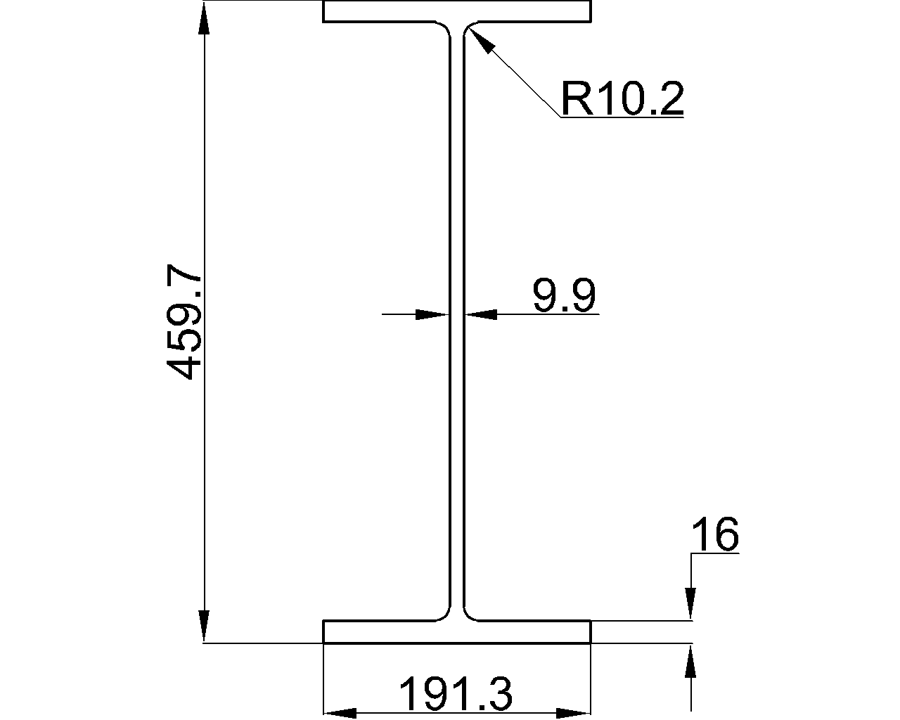
Depth : 459.7 mm
Width : 191.3 mm
Web Thickness : 9.9 mm
Flange Thickness : 16 mm
Root Fillet Radius : 10.2 mm
Sectional Area : 104.52 cm2
Unit Weight : 82 kg/m
How to read the W18x55 reference
The listed depth and width describe the overall envelope of the shape. Web thickness refers to the central vertical element, while flange thickness describes the thickness of the projecting top and bottom elements. The root fillet radius identifies the curved transition between the web and each flange, which can matter when modeling clearances, copes, and connection details.
Section information and design use
The source also reports the W18x55 sectional area and unit weight. Sectional area is used in engineering calculations involving the steel cross section, while unit weight supports quantity takeoffs and framing estimates. These values should not be treated as a complete design check: strength, stability, serviceability, connection behavior, material specification, and loading must be evaluated for the actual project.
AISC reference and CAD workflow
The page identifies AISC 360-16 as the referenced specification for the design, fabrication, and erection of steel structures in the United States. Confirm that the governing project requirements match the referenced basis before relying on the table for design or detailing.
The linked DWG file can support CAD coordination and preliminary layout. After importing it, check drawing units, layer standards, insertion orientation, and any project-specific rounding or detailing conventions. The DWG should be verified against the source dimensions before it is used for fabrication documentation.
Related reference topics
- W-shape dimensions and section terminology
- Structural steel section properties
- Steel connection and detailing concepts
- AISC design references and specification terminology
- CAD and DWG resources for structural steel
Frequently asked questions
What type of section is the W18x55?
It is identified in the source content as a W beam, also called a wide-flange shape.
What do the listed dimensions describe?
They describe the shape’s overall depth and width, web and flange thicknesses, and root fillet radius. Use the supplied reference values rather than estimating dimensions from the designation.
What is the sectional area used for?
Sectional area describes the amount of steel in the cross section and can support engineering calculations and quantity checks. It is only one input in a complete design evaluation.
Can the DWG be used directly for fabrication?
The DWG is a drafting resource. Verify its geometry, units, orientation, and project-specific requirements against the authoritative source data before using it in fabrication documents.
Does this page confirm that the W18x55 is adequate for a project?
No. Adequacy depends on loads, unbraced lengths, material requirements, connections, limit states, serviceability criteria, and the governing project specifications. A qualified engineer should complete the design verification.