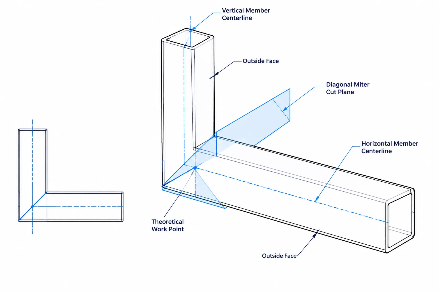
Mitered HSS corners appear in frames, equipment supports, canopies, rails, trusses, and architectural steel assemblies. Although the finished joint may look simple, its geometry can become ambiguous when drawings mix member centerlines, outside faces, theoretical intersection points, and actual cut lengths.
A dependable detail should answer four separate questions: Where do the member work lines intersect? What plane defines each cut? Which dimensions control the finished assembly? What fabrication allowances must be applied after the theoretical geometry is established? Keeping those questions separate helps prevent accumulated error and makes cut information easier to verify.
What Is a Mitered HSS Corner?
A mitered corner is formed by cutting the ends of adjoining members so their cut faces meet along the corner. For square or rectangular HSS lying in a common plane, the cuts are often arranged around a line that bisects the included angle. That familiar arrangement is only one case, however.
The geometry changes when:
- The members have different depths or widths.
- The HSS centerlines are offset.
- One member is sloped or skewed.
- The frame is not planar.
- The desired outside faces must remain flush.
- A connection plate, weld preparation, or intentional gap modifies the theoretical cut.
A miter should therefore be treated as an intersection of member geometry, not as an assumed cut angle applied to every corner.
Begin with Work Lines and the Theoretical Corner
The cleanest layout starts with member work lines. These are commonly the longitudinal centerlines of the HSS, although a project may use a face-of-steel line or another defined datum. The drawing should make that choice clear.
The intersection of the work lines establishes the theoretical corner. It is a layout reference rather than a physical point that necessarily remains on either fabricated piece. Once the work point is established, the HSS cross sections can be placed around their work lines using verified outside dimensions.
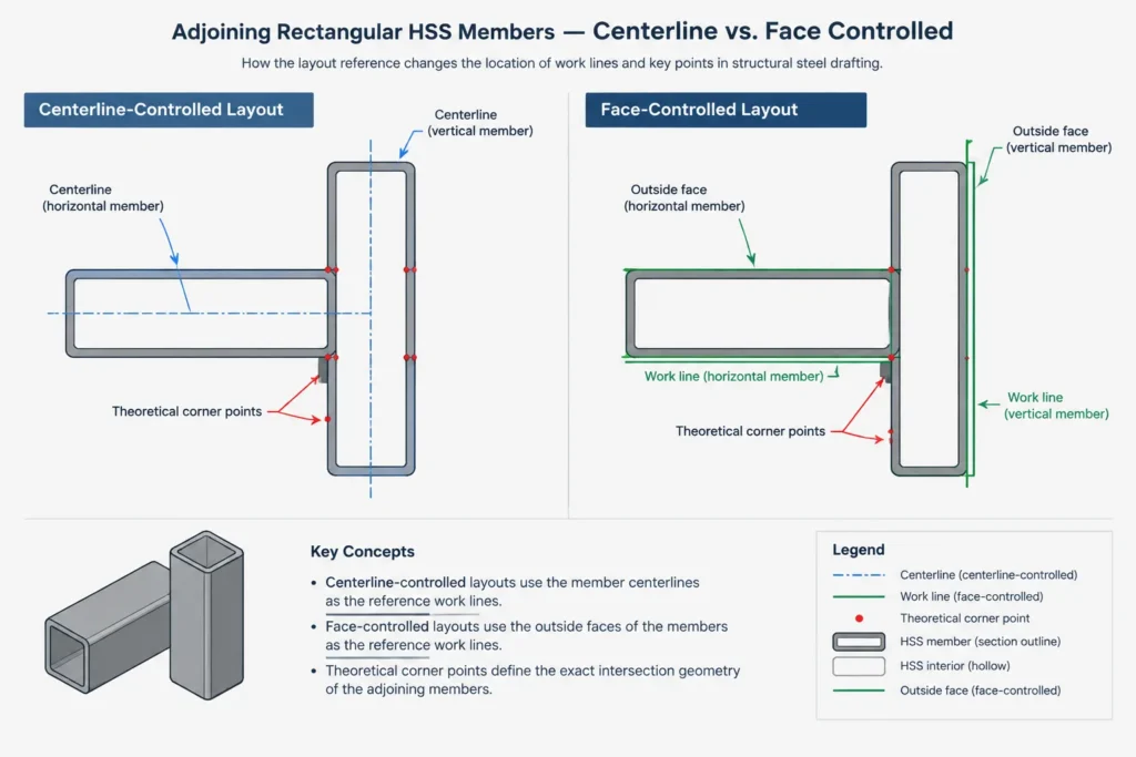
This order matters. If the outside faces are drawn first and the centerlines are inferred later, small placement errors can produce a frame with incorrect overall dimensions or inconsistent member offsets.
Centerline-Controlled Layout
Centerline dimensions are useful when the framing geometry is defined by grids, work points, or member axes. They also provide a stable reference when member sizes may change during coordination. If the HSS size changes, however, the outside envelope changes unless a face is independently controlled.
Face-Controlled Layout
Face dimensions are often important where the steel must align with cladding, glazing, equipment, guard components, or another visible surface. In that situation, the controlling face should be identified explicitly. A face-controlled member may no longer be centered on the original work line after a size substitution.
Centerline and face dimensions can coexist, but the drawing should distinguish the controlling dimensions from reference information.
The Miter Line Is Not the Same as the Cut Plane
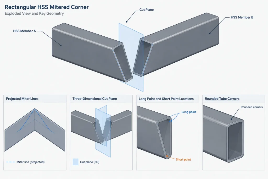
In a plan or elevation, a miter is usually shown as a diagonal line across the member. That line is only the visible projection of a three-dimensional cut plane. For planar frames made from matching square or rectangular HSS, the projected line may describe the joint adequately. More complex conditions require additional views or model-based verification.
A cut plane may intersect:
- Both side walls along straight lines.
- The top and bottom walls at different locations.
- Rounded HSS corners rather than only flat wall regions.
- A weld seam whose location may affect appearance or fit-up.
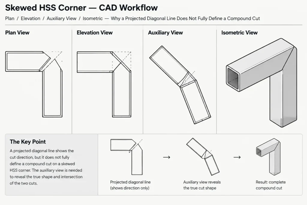
For a skewed or out-of-plane joint, a single apparent angle in elevation does not fully define the cut. A section, auxiliary view, end view, or developed cutting template may be necessary to communicate the actual shape.
Theoretical Length, Cut Length, and Finished Assembly Size
Several lengths may be associated with the same HSS member. They should not be used interchangeably.
| Term | Meaning | Typical use |
|---|---|---|
| Work-point length | Distance between defined layout points along the member work line | Framing geometry and model control |
| Long-point length | Distance to the farthest extremity of an angled cut along a stated face or corner | Saw setup and stock planning |
| Short-point length | Distance to the nearest extremity of the cut along a stated face or corner | Checking cut orientation and remaining material |
| Finished assembly dimension | Overall size of the joined frame after fit-up | Interface and erection coordination |
| Blank or rough-cut length | Material length before final end preparation | Shop processing, when specifically required |
A cut list stating only “length” can be unclear for a member with two angled ends. A useful detail identifies the measurement path, the referenced face, and whether the value is theoretical or includes approved fabrication allowances.
Do Not Treat the Weld Joint as Pure Geometry
The theoretical model may show two cut surfaces meeting exactly. The fabricated joint may require different treatment. Joint configuration, root opening, beveling, backing, access, weld sequencing, and finish requirements can all affect the final end preparation.
The detailer should not create weld preparation from appearance alone. The connection design and project requirements should establish the intended joint. Once that information is available, the theoretical miter geometry can be adjusted without losing the controlling frame dimensions.
Important coordination questions include:
- Is the visible corner intended to be sharp, blended, capped, or left as-welded?
- Is complete perimeter welding required, or is another weld arrangement shown?
- Must an HSS weld seam be placed away from a visible face or intersecting weld?
- Will internal backing, diaphragms, drain paths, or venting provisions affect the joint?
- Does grinding or finishing change the required corner profile?
These are design and fabrication issues, not values that should be inferred from a generic CAD block.
Matching and Unequal HSS Members
Matching Sections
When identical HSS members meet symmetrically in one plane, their outside faces can often be made continuous around the corner. The theoretical cut plane generally follows the angular bisector of the member work lines. Even in this straightforward condition, the drawing should show which member end is oriented toward the inside and outside of the frame.
Unequal Sections
When the members differ in depth or width, a simple bisector may not create the intended face alignment. The detailer must first decide which surfaces are to be flush. Aligning one outside face can produce a step on another face, while keeping both centerlines intersecting may offset the visible perimeter.
Unequal-section joints often benefit from a section through the corner. The section can show centerline offsets, wall relationships, and whether a closure plate or transition detail is needed. The model should not hide an unresolved mismatch inside overlapping solids.
A Practical CAD Workflow
- Establish the controlling geometry. Draw grids, work points, member axes, and any required face-of-steel boundaries.
- Insert verified HSS profiles. Use the applicable outside dimensions and wall representation. Avoid relying on an unverified nominal outline.
- Orient each member deliberately. Track major faces, corner radii, and weld-seam orientation when those features matter.
- Create the theoretical intersection. Extend the members through the work point before trimming. This preserves a clear geometric reference.
- Define the cut plane. Use the intended face alignment and joint arrangement rather than assuming the cut bisects the visible angle.
- Model both members independently. Separate solids or parts make it easier to extract cut geometry, assign marks, and detect overlap or gaps.
- Apply documented fabrication adjustments. Add joint gaps, bevels, or other end preparation only from coordinated information.
- Check the assembled envelope. Verify overall width, height, diagonals, work-point locations, and interface faces.
- Produce shop-readable views. Show enough views to define cut direction, long and short points, member rotation, and weld location.
- Compare the cut list with the model. Confirm that listed lengths use the same datums as the detailed part.
Common Detailing Errors
- Assuming every corner uses the same miter angle. This fails at unequal, offset, skewed, and nonplanar joints.
- Dimensioning to an undefined diagonal endpoint. Identify the face, corner, or work line used for the measurement.
- Using nominal HSS size as finished geometry. The drawing and model should use verified section information appropriate to the task.
- Trimming members before establishing work points. This can make later dimensional changes difficult to audit.
- Ignoring rounded corners. A cut passing through an HSS corner region may not produce the sharp intersection suggested by a simplified outline.
- Confusing joint fit with weld preparation. The visible contact line does not, by itself, define bevels or welding requirements.
- Checking only one view. A joint that looks correct in plan may contain an elevation mismatch or compound cut.
What a Clear Shop Detail Should Communicate
A practical miter detail should identify the member marks and HSS designations, the controlling work points or faces, the orientation of each part, and the dimensions needed to reproduce the cut. Additional sections should be included when the joint cannot be understood from the main view.
Shop information should also remain consistent with the assembly drawing. Part drawings may control individual cuts, while the assembly drawing controls the final frame geometry. If theoretical and fabricated dimensions differ because of an intentional joint treatment, that relationship should be visible rather than left to assumption.
Final Review Checklist
- Are the work lines and corner work point defined?
- Is the assembly controlled by centerlines, outside faces, or both?
- Does each cut represent a verified plane rather than only a projected line?
- Are long-point and short-point references unambiguous?
- Have unequal section sizes and face offsets been resolved?
- Are weld preparation and fit-up allowances based on coordinated requirements?
- Has the finished frame envelope been checked independently of the cut list?
- Do part, assembly, and model geometry use the same datum logic?
The key to reliable mitered HSS corners is separating framing geometry from fabrication treatment. Establish the work points first, derive the actual cut planes from the intended alignment, and then incorporate coordinated joint requirements. That sequence produces drawings that are easier to check, fabricate, and revise.


