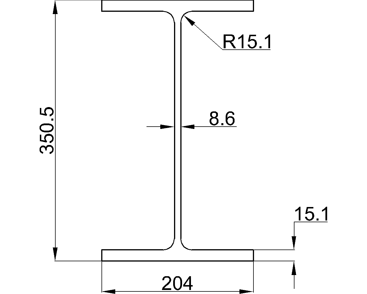
The J 127x114x27 is a taper-flange joist section reference for engineers, detailers, and steel fabricators working with European structural steel profiles. The source data identifies its governing reference, principal dimensions, radii, flange slope, sectional area, and unit weight.
Use the dimensional values below when checking drawings, comparing related joist sections, or coordinating steelwork details. For design work, confirm the applicable material specification, loading, restraint, connection arrangement, and project requirements separately.
J 127x114x27
Joists With Taper Flange Sections
refer to : EN 10365:2017
a European standard that defines the dimensions, tolerances, and sectional properties for hot-rolled steel channels, I-beams, and H-beams used in construction and engineering. It ensures uniformity and compatibility across European structural steel products.
Dimension : 127×114.3×7.4×11.4
Depth : 127 mm
Width : 114.3 mm
Web Thickness : 7.4 mm
Flange Thickness : 11.4 mm
Root Fillet Radius : 9.9 mm
Toe radius : 5 mm
Flange slope : 14.05%
Sectional Area : 33.8 cm2
Unit Weight : 26.5 kg/m
How to read the J 127x114x27 reference
The dimension string describes the principal envelope and thickness information for the section. Depth and width indicate the overall profile dimensions, while web and flange thicknesses describe the main steel elements that form the joist. These values are useful when checking clearances, support details, connection geometry, and drawing compatibility.
Radii and flange slope
The root fillet radius and toe radius describe the curved transitions between the web, flange, and flange edge. They matter when detailing fittings, checking contact surfaces, or preparing accurate CAD geometry. The flange slope identifies the inclined flange arrangement associated with this taper-flange section.
Sectional area and unit weight
Sectional area is a geometric property used in steel quantity checks and in engineering calculations where the area of the profile is required. Unit weight supports mass estimates, handling information, and material takeoffs. Neither value should be used alone to establish structural adequacy.
Using the standard reference and DWG file
The page cites EN 10365:2017 as the reference for dimensions, tolerances, and sectional properties of the listed hot-rolled steel profiles. Treat the standard reference and the local source table as the controlling dimensional references for coordination, while checking project specifications before fabrication.
The downloadable DWG can help with drafting and layout workflows. Verify units, insertion scale, layer conventions, and the drawing geometry against the published source values before using the file in a production drawing. Related internal resources may include steel section terminology, section property explanations, structural steel connections, and CAD/DWG drafting guidance.
Frequently asked questions
What type of section is J 127x114x27?
It is identified as a joist with taper-flange geometry. The page provides its dimensions and associated geometric and mass properties.
What does the dimension string represent?
The dimension string summarizes the principal size and thickness information reported for the profile. Refer to the individual depth, width, web thickness, and flange thickness entries for the detailed breakdown.
Why are the root and toe radii listed?
Radii describe the curved portions of the rolled profile. They are relevant when checking clearances, connection details, contact areas, and CAD representations.
Can the listed section properties replace a structural design check?
No. The listed properties are reference data. Structural verification also depends on the material, loads, restraints, connection details, applicable design rules, and project conditions.
What is the DWG file used for?
The DWG is a drafting reference for representing the section in CAD. Confirm its scale, units, and geometry against the source data before issuing design or fabrication documents.