A plate drawing can appear fully dimensioned and still leave its hole pattern open to interpretation. The problem is often not missing dimensions, but an unclear coordinate system. If the fabricator cannot determine which plate edges, centerlines, or work points control the holes, small drafting ambiguities can become layout errors, mirrored parts, or incompatible connection assemblies.
A reliable hole layout establishes a stable origin, identifies the controlling directions, and distinguishes fabrication dimensions from convenient reference information. The same approach is useful for base plates, end plates, gusset plates, splice plates, clip angles, stiffeners, and other components with drilled, punched, or cut holes.
What a hole coordinate actually defines
A round hole is normally located by its center. In a two-dimensional plate view, that center requires a position in each controlling direction. These directions may be shown as horizontal and vertical dimensions, local X and Y coordinates, distances from plate edges, or offsets from established centerlines.
A complete hole definition also requires information beyond location. Depending on the connection, the drawing may need to identify:
- Hole diameter or the applicable hole designation
- Whether the opening is round, slotted, or another approved shape
- Slot length and width when required by the project documents
- Slot orientation relative to the plate or member
- The quantity of identical holes in a pattern
- Whether the dimensions apply to the near face, far face, or developed plate
- Which holes are shop-produced and which, if any, are field-made
The contract documents, connection design, and fabricator requirements govern these items. A CAD point at the correct location does not by itself provide a complete fabrication definition.
Selecting a stable datum
A datum is the reference from which dimensions or coordinates are measured. Good datums correspond to features that can be identified consistently during detailing, fabrication, and inspection.
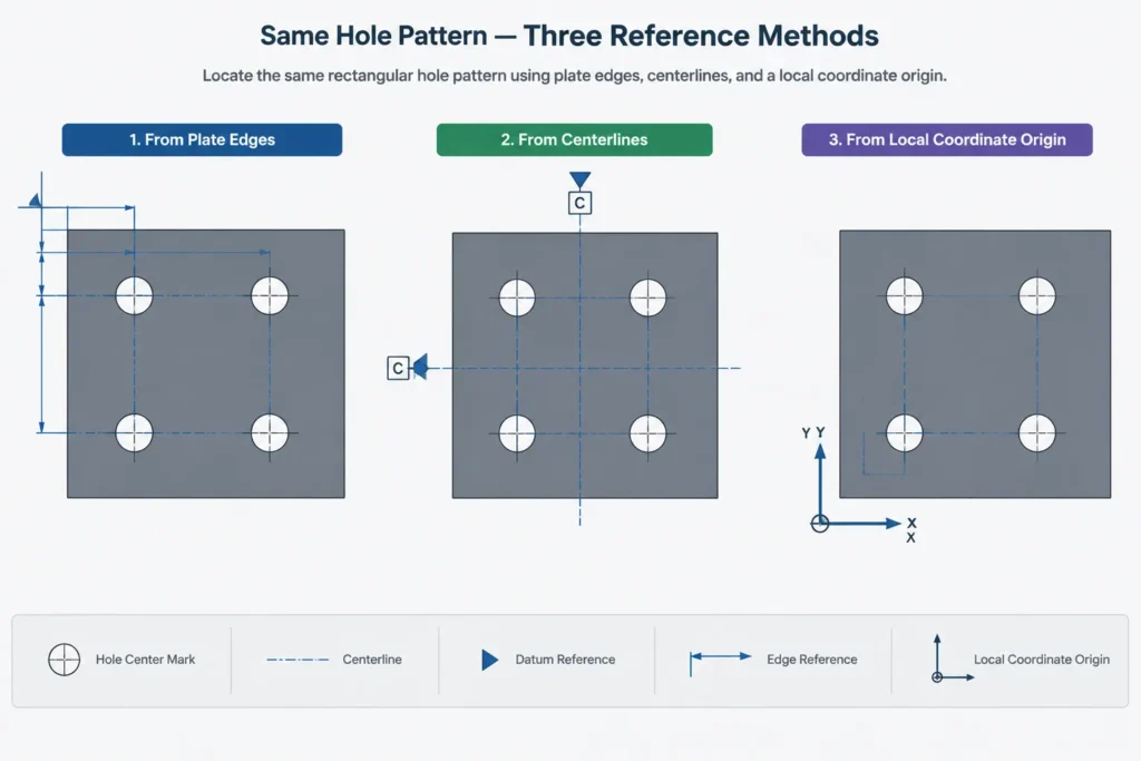
Plate edges
A straight plate edge can be an effective datum when the holes are intended to maintain a controlled edge distance. This is common for rectangular plates and other parts whose finished edges are established before the holes are produced.
Not every visible edge is equally reliable. A beveled edge, clipped corner, irregular contour, or edge affected by a later cut may be a poor origin. The drafter should reference the underlying straight edge or another stable feature rather than an incidental point on the contour.
Plate centerlines
Centerlines are useful for symmetrical patterns and parts that may vary equally on opposite sides of an axis. A centered hole group can be easier to understand when dimensions originate from the plate centerline instead of being chained from both outside edges.
Centerline control also makes design intent clearer. If a plate width changes while the connection remains centered, the hole pattern can stay tied to the intended axis rather than shifting with one edge.
Member work lines and connection axes
Some hole groups are controlled by the supported member, column centerline, beam web, brace work line, or another connection axis rather than by the plate boundary. This commonly occurs with gusset plates and irregular connection plates. In these cases, the plate outline may be developed around a connection geometry that already exists.
The drawing should show how the work line relates to the plate. Otherwise, a fabricator may correctly lay out the holes from the plate edges while still producing a part that does not align with the adjoining member.
Coordinate dimensions versus conventional dimensions
Hole centers can be communicated with dimension strings or with an ordinate-style coordinate system. Either method can work when the origin and direction are unmistakable.
| Method | Useful characteristics | Potential concern |
|---|---|---|
| Edge-to-center dimensions | Directly communicates the relationship between holes and finished plate edges | Long chains can accumulate interpretation or production errors |
| Centerline-based dimensions | Clearly expresses symmetry and alignment with member axes | The centerline must be physically and graphically identifiable |
| Baseline dimensions | Each location returns to a common datum | A crowded view can become difficult to read |
| Ordinate coordinates | Efficient for numerous holes and irregular patterns | An unclear origin or reversed axis can affect the entire pattern |
| Hole table | Organizes coordinates, sizes, and types without filling the view with dimensions | Hole labels must correspond unambiguously to the graphical view |
Mixing methods is sometimes appropriate, but duplicate dimensions should not create competing controls. If a coordinate table establishes the hole centers, added edge distances may be marked or presented as reference information when they are included only as checks.
Establishing local X and Y directions
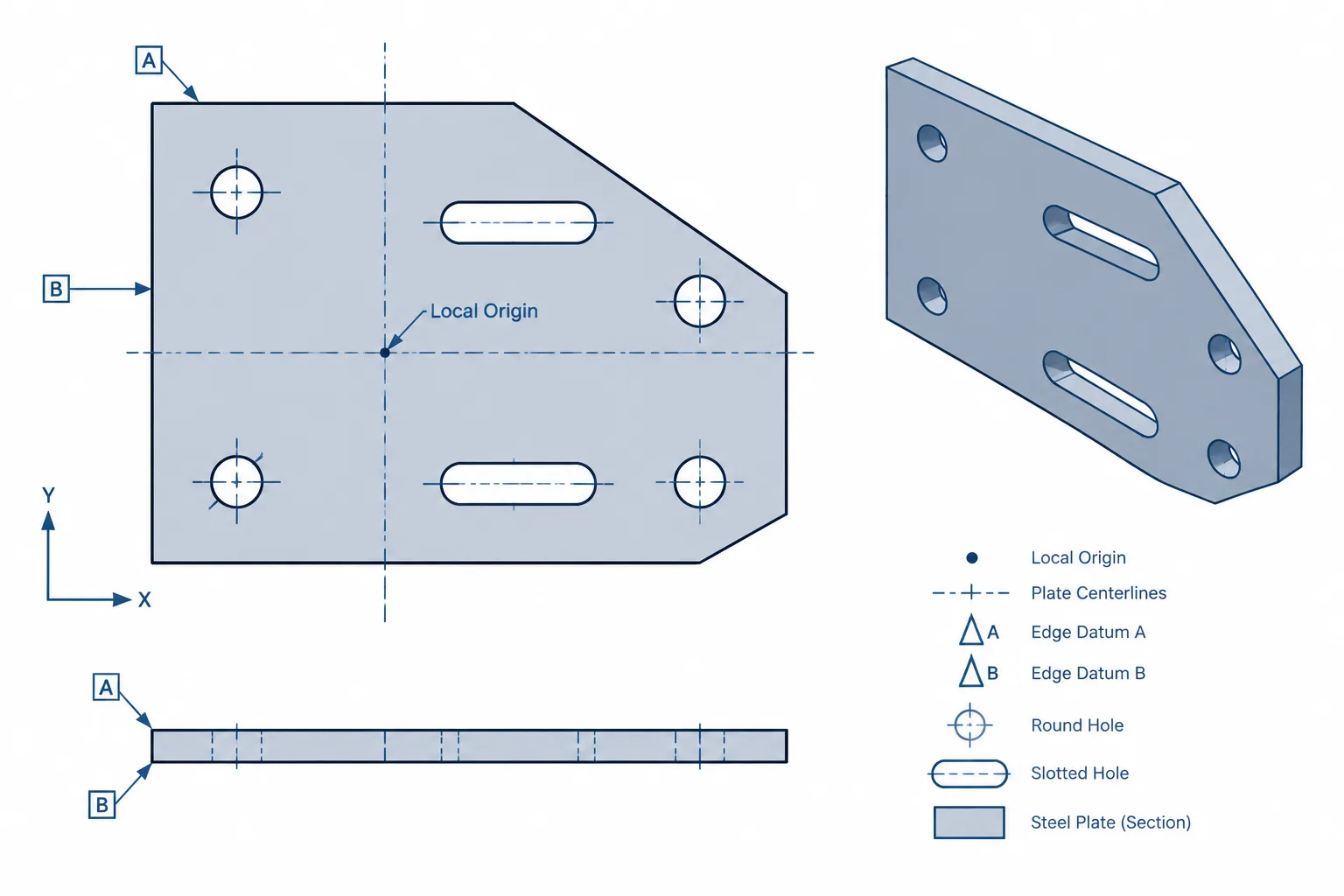
Global model coordinates are rarely the clearest way to manufacture an individual plate. A local plate coordinate system is usually easier to read and verify. The origin might be placed at a corner, at the intersection of centerlines, or at a defined work point.
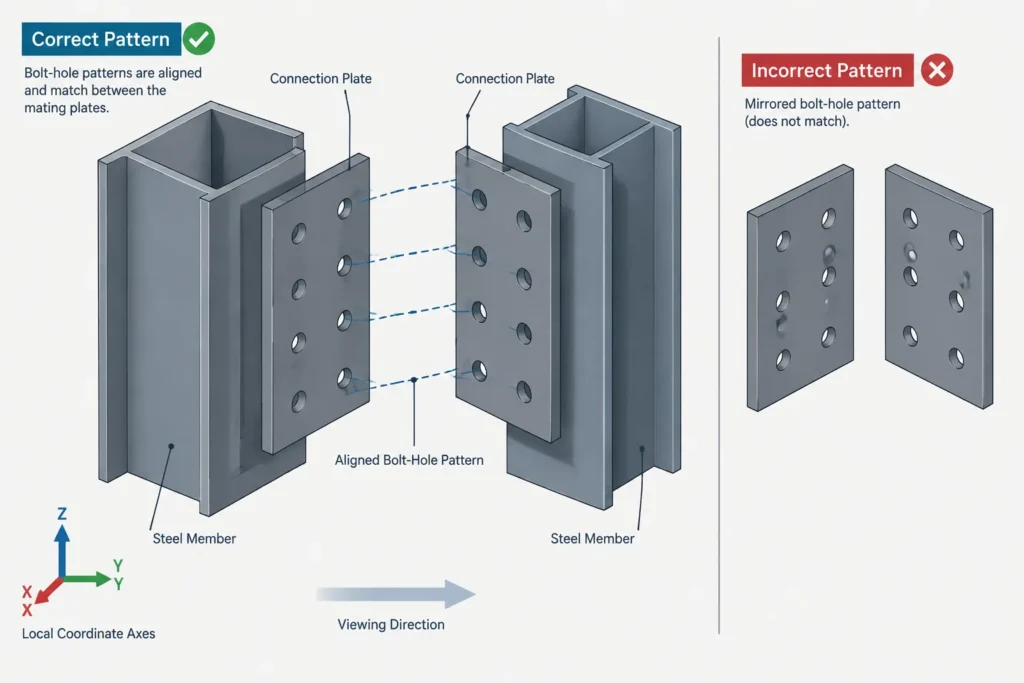
The drawing should make the positive directions obvious. This becomes especially important when a part is rotated on a sheet, viewed from its opposite face, or exported from a model. A coordinate list that is correct in the model can produce a mirrored pattern if the fabrication view uses a different viewing direction.
For an irregular plate, the local axes should not be inferred solely from the sheet border. Show them relative to a controlling plate edge, member axis, or work line. The local system should remain meaningful even if the detail is moved or rotated during drawing layout.
Slots require orientation as well as a center
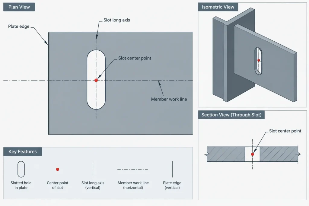
The center of a slotted hole locates the opening, but it does not define the direction of its long axis. Slot orientation should be shown relative to a clearly identified feature, such as the plate edge, member axis, bolt line, or local coordinate direction.
Words such as horizontal and vertical can become ambiguous when a detail is rotated or when the plate is installed on a slope. Terms tied to the part geometry, such as parallel to the member axis or perpendicular to the plate edge, are often more durable. A graphical slot representation can support the callout, but the drawing should not depend on an exaggerated symbol alone.
Special considerations for irregular and bent plates
Irregular plate boundaries
On a gusset or shaped connection plate, avoid locating holes from a sloping edge unless that edge truly controls the connection. A small change in the edge angle can alter the interpreted coordinate. Work lines, orthogonal datums, or a known plate corner generally provide more stable control.
Bent plates
A hole near a bend may be dimensioned in the formed condition or on the flat development, depending on the fabrication workflow and project requirements. These are not automatically interchangeable. The detail should state which representation controls and should coordinate hole locations with bend lines, bend orientation, and the intended finished geometry.
Skewed connection plates
When a plate is skewed relative to the main framing, model coordinates and plate-local coordinates may differ substantially. Transforming the pattern into a local view makes fabrication easier, but the transformation should be checked against the connection work points and mating holes.
CAD workflow for dependable hole patterns
A practical CAD workflow separates design intent from graphical repetition:
- Confirm the connection axes, plate orientation, and viewing direction.
- Create the plate outline from the controlling geometry.
- Establish a local origin and two clearly defined directions.
- Place hole centers as points or center marks before drawing hole boundaries.
- Build repeated patterns from controlled spacing or verified coordinates.
- Assign slot orientation independently from slot center location.
- Dimension from the selected datum rather than from copied geometry.
- Compare the hole group with the mating member or plate in the model.
- Check the plotted shop drawing independently of the model view.
Associative constraints, blocks, and parametric tools can reduce repetitive work, but they do not decide which datum should control. Automated patterns can also preserve an incorrect origin or propagate a mirrored condition. Human review remains necessary.
Common hole-coordinate failures
- Mixed origins: Some holes are measured from one edge while others use an opposite edge without a clear reason.
- Closed dimension chains: Multiple dimensions define the same geometry and can conflict after revisions.
- Unidentified reference dimensions: A check dimension appears to control fabrication even though another value is intended to govern.
- Mirrored views: The drawing does not state which face of the plate is shown.
- Missing slot direction: The slot center is located, but its long-axis orientation is undefined.
- Datum on a changing contour: Holes are tied to a cope, clip, bevel, or sloping edge that is not the true connection control.
- Model-to-drawing mismatch: Coordinates come from local model axes while the detail labels them as sheet-horizontal and sheet-vertical.
Final detailing checklist
Before releasing a plate detail, verify that a reviewer can answer the following questions without opening the CAD model:
- What feature is the coordinate origin?
- Which directions define the hole locations?
- Which dimensions control and which are references?
- Is the shown face of the plate clear?
- Are all hole and slot types identified?
- Is every slot orientation unambiguous?
- Does the hole group align with the mating member or connection plate?
- Will the datum remain valid if the plate outline changes?
- Do the drawing, model, and any fabrication data represent the same geometry?
Clear steel plate hole coordinates are not simply a matter of adding more dimensions. The objective is to communicate one stable geometric definition that can be modeled, fabricated, inspected, and assembled without guessing. A carefully selected datum and an explicit local coordinate system make even complex plate patterns easier to understand and verify.