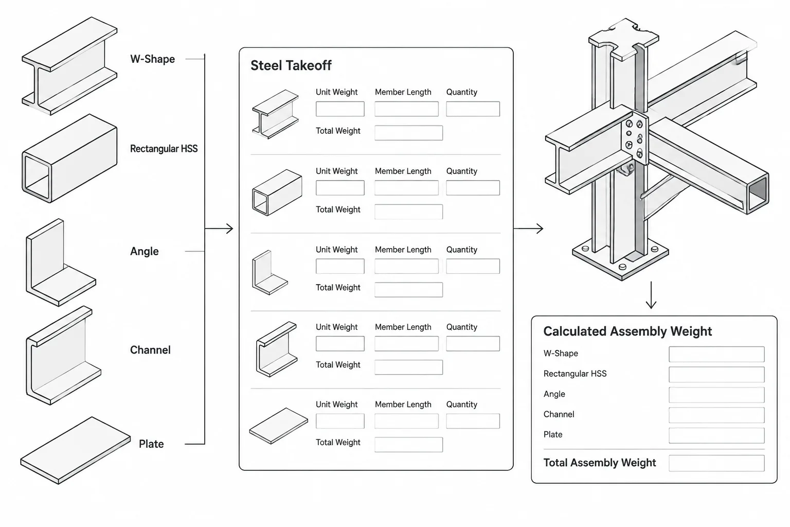
A structural steel member weight calculation often appears simple: multiply a tabulated weight per unit length by the member length. That is the correct starting point for rolled shapes and HSS, but reliable results depend on using the right table entry, the right length, and the right definition of what the calculated weight represents.
Design loads, material takeoffs, bills of material, shipping estimates, and erection planning do not always require the same level of detail. A beam line item may represent only the main shape, while a fabricated assembly can also include plates, stiffeners, connection material, bolts, weld metal, and coatings. Understanding these boundaries prevents a clean-looking spreadsheet from producing a misleading total.
The basic calculation for rolled shapes and HSS
Published steel shape tables commonly provide a nominal weight per unit length. In U.S. customary units, this is typically expressed in pounds per foot. Metric references generally use mass per unit length, such as kilograms per meter.
For a straight member, the basic relationship is:
Member weight = tabulated weight per unit length × member length
For multiple identical members:
Total line-item weight = unit weight × length × quantity
This method applies to W-shapes, channels, angles, structural tees, HP shapes, HSS, and other products when a verified unit-weight value is available. The arithmetic is straightforward; selecting and interpreting the inputs is the more important task.
Do not assume every shape designation contains its weight
Some rolled-shape designations include a nominal weight per unit length as part of the name. A W-shape designation, for example, identifies a nominal depth and nominal weight. Similar naming patterns are used for certain other rolled families.
Other designations describe geometry instead. Angle names identify leg dimensions and thickness, while rectangular and square HSS names identify outside dimensions and nominal wall thickness. Their unit weights should be obtained from a verified shape table rather than inferred from one number in the designation.
Even when weight appears in a shape name, the corresponding database or table entry should remain the controlling source for calculations and CAD data. The designation is an identifier, not a replacement for verified tabulated properties.
Select the correct member length
A weight calculation is only as reliable as its length input. Structural drawings and fabrication records may contain several lengths for the same member:
- Work-point length: the distance between framing or layout reference points.
- Detailed length: the modeled or dimensioned extent of the member before some end preparation is considered.
- Cut length: the physical length used to manufacture the piece.
- Ordered length: the stock or procurement length purchased before cutting.
For a bill of material describing the finished main member, the cut or modeled physical length is generally more relevant than a grid-to-grid work-point distance. For purchasing, stock optimization, or scrap planning, ordered length may be the necessary input. These values should not be mixed in one total without identifying their purpose.
Sloped and skewed members
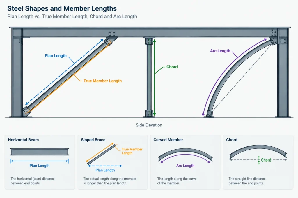
A sloped beam or brace is longer than its plan projection. Multiplying unit weight by the horizontal plan length understates the member weight. Use the true three-dimensional member length from coordinated geometry.
Skew alone does not necessarily change length, but it can make projected dimensions unreliable. Confirm whether the reported length is measured along the member axis, along a global axis, or between work points.
Curved members
For a curved member, establish which path defines length. Depending on the modeling and fabrication convention, the reference may be the member centerline, section insertion line, or another controlled curve. A chord length is not interchangeable with arc length. The takeoff method should use the same path employed by the detailing model and fabricator.
Nominal weight is not the same as exact as-fabricated weight
Tabulated unit weights are reference values based on the published section data. Actual manufactured products are subject to permitted dimensional and mass variation. Therefore, a table-based result should not be presented as the exact scale weight of an individual piece.
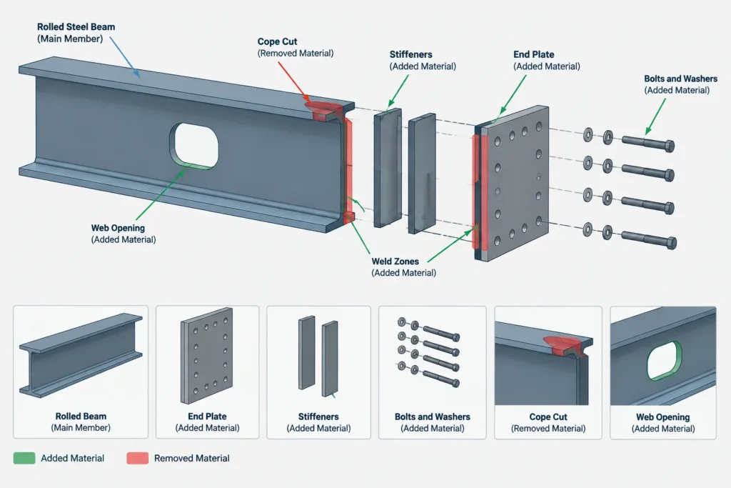
Fabrication also changes the assembly:
- Copes, notches, slots, and large openings remove material.
- End plates, stiffeners, seats, tabs, and reinforcement add material.
- Bolts, nuts, washers, and weld metal add weight.
- Galvanizing, paint, fire protection, and other applied systems may affect shipping or handling weight.
Routine estimating often leaves small holes and minor cuts within the nominal main-member weight because calculating every subtraction can add effort without materially improving the estimate. That convention may be inappropriate for lifting studies, shipping limits, center-of-gravity work, or unusually perforated members. The intended use should determine the required precision.
Calculating plate and irregular-part weight
Plates do not normally have a rolled-shape weight-per-length entry tied to a shape designation. Their theoretical weight is obtained from volume and the density adopted for the specified material:
Plate weight = plan area × thickness × material density
For a rectangular plate, plan area is width multiplied by length. For gussets, tapered plates, rings, curved plates, or other irregular profiles, a closed CAD boundary can provide the plan area. Multiply that area by the specified thickness and a verified density value using a consistent unit system.
CAD area is useful only when the profile is trustworthy. Before using it, check for open polylines, overlapping segments, duplicated boundaries, unintended internal loops, and incorrect drawing units. Determine whether holes should be deducted and whether corner clips, notches, or weld-access features are included in the boundary.
Flat plate versus formed plate
A bent plate should generally be evaluated from its developed flat geometry when material quantity is the objective. A projected elevation or bounding box can misrepresent the actual plate area. Confirm that the flat pattern accounts for the fabrication method and that it has not been scaled or simplified for presentation.
Keep weight, mass, and force terminology clear
U.S. fabrication documents commonly use the word weight for values expressed in pounds and pounds per foot. Metric shape references commonly list mass per unit length. These terms are often used casually in takeoff workflows, but they should not be mixed without a defined conversion process.
Keep each calculation in one unit system until the result is complete. A common failure is combining a unit weight in pounds per foot with a length reported in inches, or combining kilograms per meter with model geometry stored in millimeters. Convert the length deliberately before multiplication and label the result.
| Input | Question to verify | Typical risk |
|---|---|---|
| Shape designation | Does it match the specified family and size exactly? | Using a similar but different section |
| Unit weight or mass | Did it come from a verified table or database? | Inferring weight from designation geometry |
| Length | Is it work-point, cut, modeled, or ordered length? | Using a projected or procurement length |
| Quantity | Does it count pieces, assemblies, or both? | Duplicating nested parts or missing mirrored pieces |
| Added material | Are plates and connection parts included separately? | Counting attachments twice |
| Removed material | Does the required accuracy justify deductions? | Overstating highly cut or perforated members |
Organizing a CAD or spreadsheet takeoff
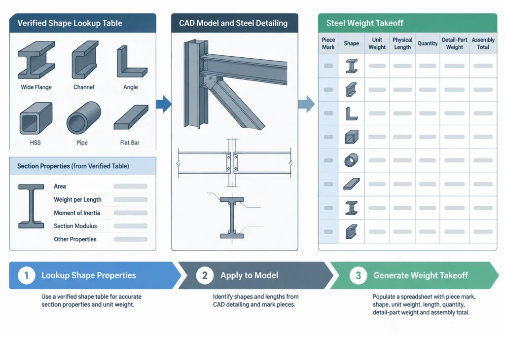
A useful takeoff separates source data from calculated results. Recommended fields include piece mark, shape or plate description, verified unit weight, physical length, quantity, calculated main-material weight, attachment weight, and assembly total. Add a units field when data may arrive from more than one system.
Avoid typing the same section weight repeatedly into individual rows. A controlled lookup table reduces transcription errors and makes shape substitutions easier to audit. The lookup key must distinguish shape families; a nominal depth alone is never enough to identify a section.
When extracting lengths from CAD or BIM, document which object property is being used. A centerline length, bounding-box length, and end-to-end solid length may differ. Test the workflow on several members with known geometry before applying it to an entire model.
Choose the calculation boundary before reporting totals
Every reported weight should state what it includes. Useful categories include:
- Main-member weight: rolled shape or HSS only.
- Detail-part weight: plates, angles, tees, or other attached pieces.
- Assembly weight: main member plus designated shop-attached material.
- Shipping weight: the defined shipment package, potentially including loose items or protective material.
- Procurement quantity: ordered stock before cuts and scrap.
These totals answer different questions. An assembly total may help with shop handling, while an erection lift requires a project-specific review of the actual lifted configuration. A table-based takeoff should not be treated as a verified lifting weight without checking the completed fabrication model, attachments, temporary hardware, and handling arrangement.
Final checking workflow
- Confirm the exact shape designation or plate material description.
- Retrieve unit weight from a verified shape source rather than estimating it from nominal dimensions.
- Identify the correct physical, curved, or developed length for the purpose of the takeoff.
- Normalize all inputs to a consistent unit system.
- Apply quantity only after confirming what one row represents.
- Add separate detail parts and avoid counting modeled attachments twice.
- Decide whether major cuts or openings require material deductions.
- Label the result as main-member, assembly, shipping, or procurement weight.
- Spot-check selected members with an independent calculation.
The multiplication behind a structural steel member weight calculation is simple. Reliable results come from disciplined data selection: verified unit weights, controlled length definitions, consistent units, and a clearly stated calculation boundary.


