Beam reactions on structural steel drawings communicate the forces that connections and supporting members may need to transfer. They are not dimensions, and they do not define a connection by themselves. A reaction note must be interpreted together with its load basis, direction, point of application, member orientation, and any project-specific connection criteria.
This distinction matters throughout the drawing workflow. Engineers use reactions to communicate design demand, connection designers use them to select and check connection components, and detailers use the resulting connection information to produce coordinated shop geometry. If any part of that information chain is unclear, a seemingly simple reaction value can be applied to the wrong beam end, axis, or load case.
What a beam reaction represents
A reaction is the force or moment developed where a member is supported or connected. For a steel beam, reactions are commonly associated with its two ends, but additional reactions may occur at intermediate supports, hangers, braces, transfer points, or other load paths.
The reaction shown on a drawing may represent one of several things:
- A support force obtained from the structural analysis model
- A governing value selected from multiple load combinations
- A minimum connection design force established by the project criteria
- A service-level force used for a particular check
- A strength-level or otherwise factored force used for connection design
- A force envelope in which different components do not necessarily occur at the same time
Because these possibilities are not interchangeable, the reaction schedule heading, drawing notes, connection specifications, and design criteria should be read before using the listed values.
Common force and moment components
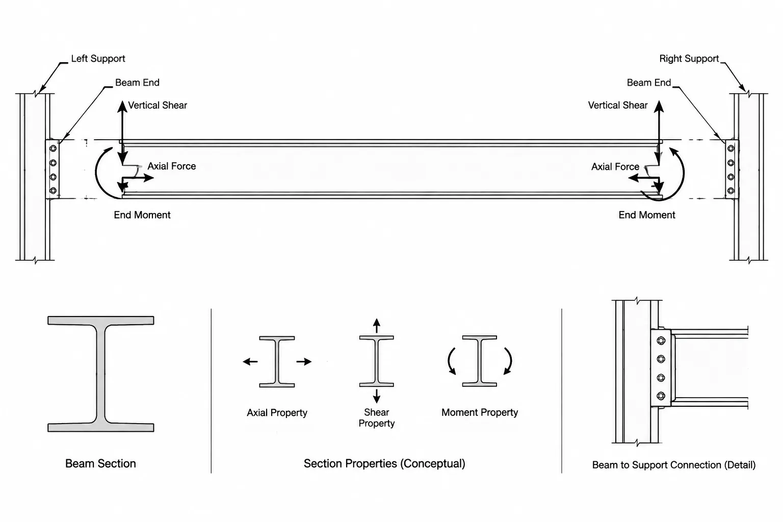
A beam end can transfer more than vertical shear. The exact components depend on the structural system and the intended connection behavior.
| Component | Typical meaning | Coordination concern |
|---|---|---|
| Vertical shear | Force acting vertically at the beam support | Often governs the primary demand for a simple shear connection |
| Axial force | Force acting along the member axis | May place the connection in tension or compression and alter the load path |
| Horizontal transverse force | Force perpendicular to the member axis in plan | May be associated with bracing, diaphragm action, or lateral framing effects |
| End moment | Moment transferred through the beam end | Requires confirmation that the connection is intended to resist moment |
| Torsion | Twisting moment about the member axis | Can affect connection geometry, supporting elements, and local reinforcement |
Symbols vary among engineering offices and software outputs. A letter such as V, R, P, or M should not be interpreted without checking the schedule legend and axis convention. The same symbol can have different meanings on different projects.
Why beam-end identification matters
A beam may have different reactions at its two ends because of unequal spans, nonuniform loading, cantilevers, framing offsets, or differing support conditions. A reaction schedule therefore needs an unambiguous method for identifying each end.
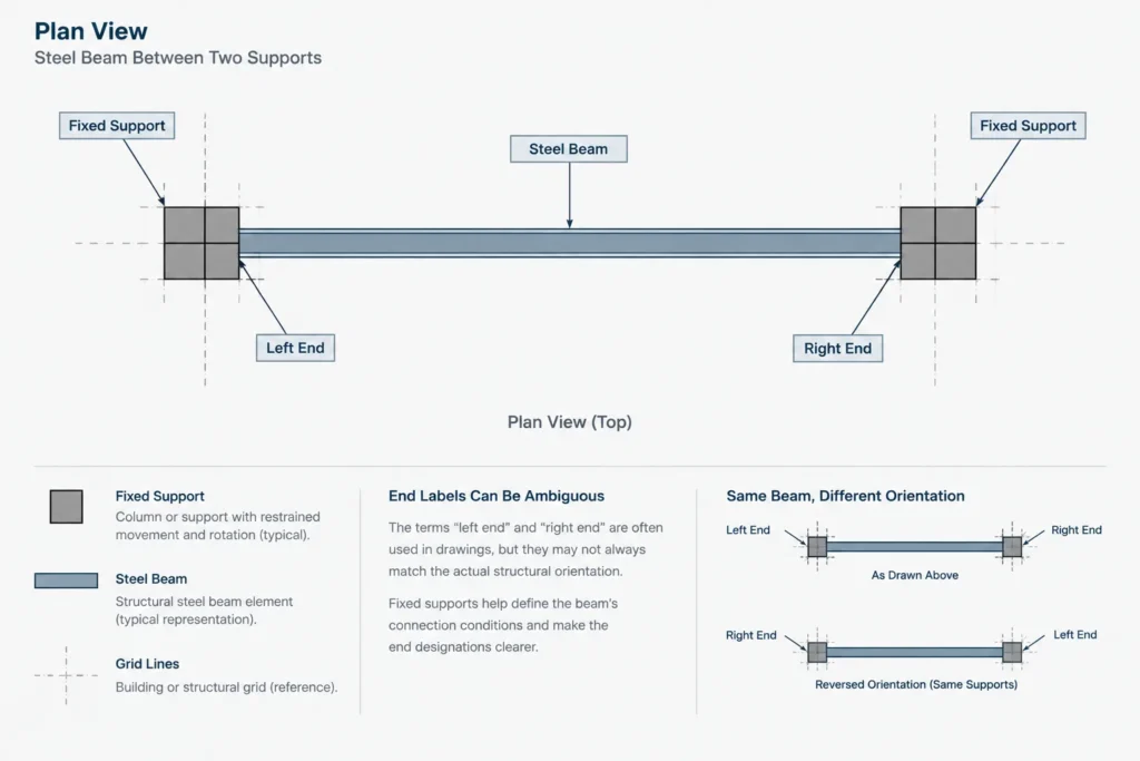
Common methods include:
- Left and right ends as viewed on a designated plan
- Start and end based on the analysis or modeling direction
- Named grid intersections
- Column, girder, or support marks
- End numbers shown on a framing diagram
“Left” and “right” are especially vulnerable to mistakes. A beam viewed from the opposite direction appears reversed, and a mirrored erection plan can create additional confusion. Grid-based or support-based end labels are generally easier to trace because they refer to fixed project locations.
CAD and building-model member directions can also affect exported end data. A member drawn from one grid to another may have its local start end at the first picked point, even when that end appears on the right side of a sheet. Do not assume that local end designations match visual sheet orientation.
Global axes, local axes, and sign conventions
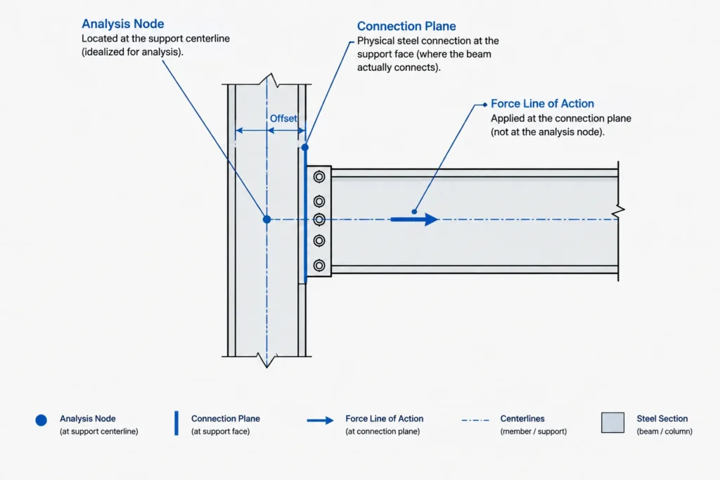
Reaction signs only make sense when their reference axes are known. Structural analysis models commonly track forces using a combination of global project axes and local member axes. A positive axial force, transverse force, or end moment may therefore depend on the software convention and member direction.
A useful reaction presentation should make the practical design meaning clear. For example, it should distinguish tension from compression and indicate the physical direction of lateral forces or moments. If a schedule only contains positive and negative values without an axis diagram or legend, the connection designer should request clarification rather than infer the convention.
Member rotation adds another layer. A sloped, skewed, or rotated member can have local force components that do not align with plan north, project vertical, or the supporting member axes. For these conditions, a small orientation sketch can be more reliable than a dense notation string.
Reaction location and connection eccentricity
The point at which a reaction is reported affects how it is used. An analysis result may be located at a member node, support centerline, column centerline, beam work point, face of support, or an offset point represented by rigid links or end offsets.
If the actual connection transfers force at a different location, the offset can introduce an additional moment. For example, a vertical force reported at a support centerline is not automatically equivalent to the same force acting at a connection plane some distance away. The engineering model may already account for that eccentricity, or the connection design may need to address it separately.
Before using a reaction, confirm:
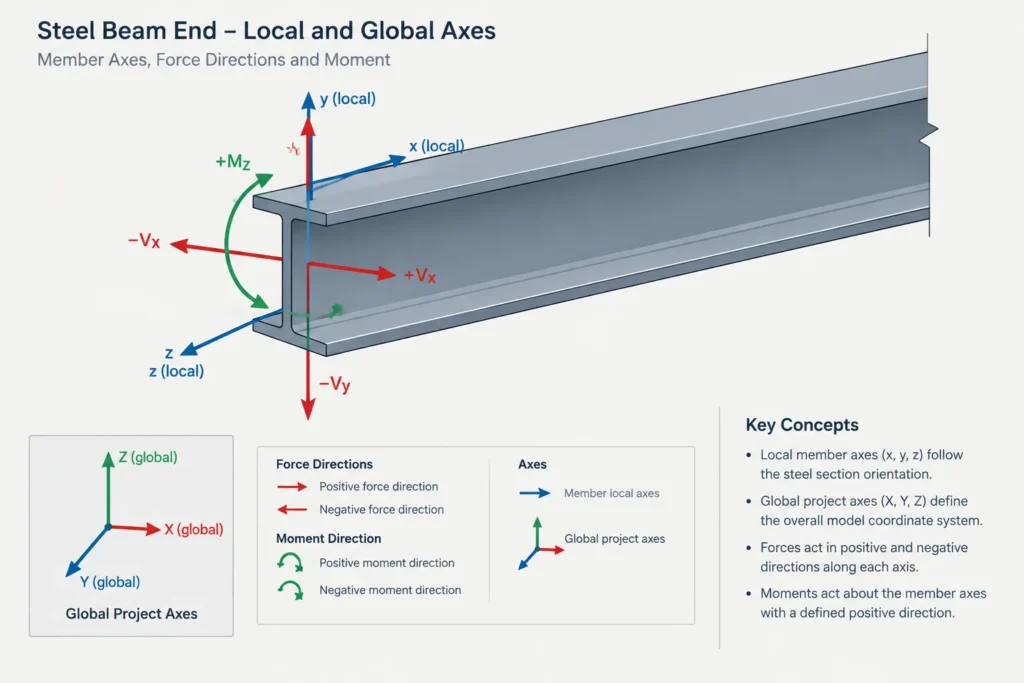
- The point where the force is reported
- The plane where the physical connection transfers the force
- Whether model offsets were included
- Whether the listed moment already includes eccentricity effects
- Whether the supporting member must be checked for local effects
Maximum values and force envelopes
A reaction schedule may list maximum shear, maximum axial force, and maximum moment in adjacent columns. Those maximum values may come from different load combinations. Combining all maxima into one artificial load case can be overly conservative or otherwise inconsistent with the intended design basis.
Conversely, designing for each component independently may miss a governing combined-force condition. The schedule should indicate whether the values are concurrent, independently enveloped, or grouped into specific load cases. Where interaction is important, connection design information may need several force sets rather than one row of maximum values.
Reversals also matter. A connection subject to both positive and negative axial force, uplift and downward force, or opposite moment directions may require different detailing from a connection designed for one-directional demand. A single unsigned maximum can hide this behavior.
Reactions do not define the complete connection
Even a clearly documented reaction does not establish every connection requirement. The designer and detailer may also need to know the intended connection type, rotational behavior, movement allowance, available connection zone, supporting-member limitations, and whether loads from other members interact at the same location.
Connection geometry must remain compatible with the actual steel shapes. Beam depth, web thickness, flange geometry, rolled fillets, cope dimensions, bolt access, weld access, and support orientation can all affect whether a proposed detail fits. Shape database information and CAD profiles are useful for checking this geometry, but they do not replace the engineering evaluation of the connection.
A practical drawing review workflow
1. Identify the member and both supports
Match the beam mark to the correct plan location, elevation, and support marks. Confirm that revisions have not changed the beam size, span, support, or orientation.
2. Read the schedule heading and notes
Determine the load basis, units, force directions, sign convention, and whether values are reactions, minimum design forces, or envelopes.
3. Map each value to a physical beam end
Use grids or support marks whenever available. Do not rely solely on left/right appearance or CAD draw direction.
4. Check all listed components
Look beyond vertical shear. Note axial force, transverse force, moment, torsion, uplift, and reversals where provided.
5. Confirm the point of application
Relate the analysis location to the actual connection plane and identify any unresolved eccentricity.
6. Compare the demand with the intended detail
Verify that the connection concept is consistent with the force types and expected behavior. A detail presented as a simple shear connection should not silently be used where moment transfer is required.
7. Coordinate changes
If framing geometry, member size, support orientation, or connection location changes, determine whether updated reactions are required. Do not assume an earlier schedule remains valid after a structural revision.
Clear reaction presentation on drawings
Reaction information is easiest to use when it is traceable rather than merely compact. A good presentation identifies the member, each end, the units, the force components, the directional convention, and the load basis. It also distinguishes actual analysis output from project minimums or connection design criteria.
Where unusual geometry exists, add a diagram showing the member axis and force directions. Where several force combinations govern, provide organized force sets instead of unrelated maxima. Most importantly, keep the reaction information coordinated with current framing plans and member marks.
Beam reactions form a bridge between structural analysis and fabricated steel. Treating them as complete, location-specific force information—not just numbers beside a beam mark—reduces interpretation errors and supports more reliable connection design, detailing, and review.