Bolted steel beam splices join separate member segments so they can be fabricated, shipped, erected, and connected as required by the project. Although a splice may look like a straightforward group of plates and bolts, its successful detailing depends on much more than copying a connection pattern onto two beam ends.
The detailer must understand which components transfer the required forces, how the two beam segments are positioned relative to one another, and which dimensions control shop fabrication versus field fit-up. The engineer’s connection design governs plate sizes, bolt arrangements, welds, material requirements, and required strengths. The detailing task is to translate that design into coordinated geometry without obscuring the intended load path.
What a Bolted Beam Splice Does
A beam splice creates continuity between two portions of a structural member. The forces crossing the splice can include shear, moment, axial force, or a combination of these effects. The required connection components therefore vary with the design intent.
Common configurations include:
- Web-only splices: Plates connect the beam webs. The connection may be intended primarily to transfer shear, although the actual design intent must be confirmed.
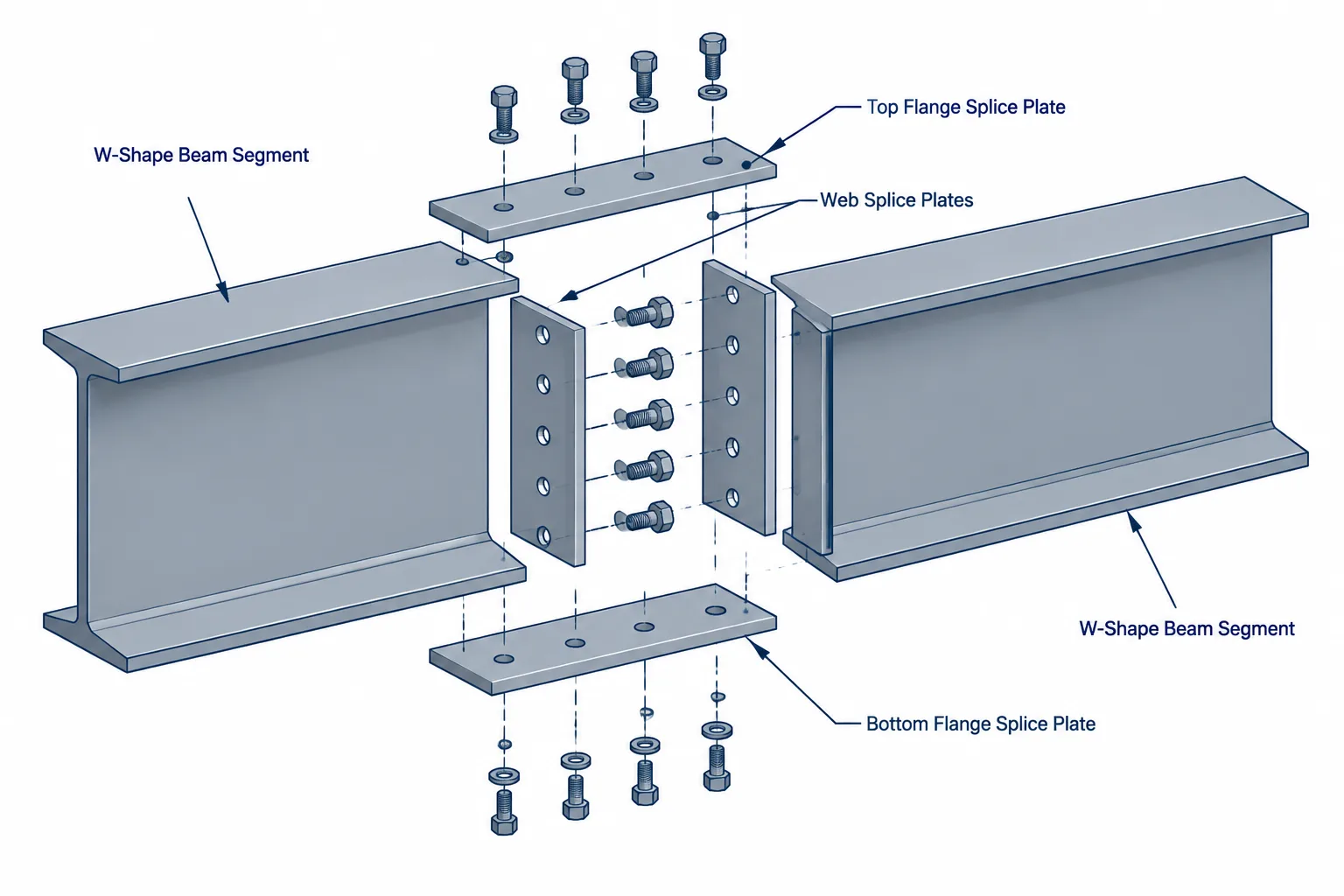
- Web-and-flange splices: Web plates and flange plates work together. The flange components commonly participate in transferring flexural forces, while the web components commonly participate in shear transfer.
- One-sided web plates: A plate is placed on one face of the web where permitted by the engineered detail.
- Double-sided web plates: Plates occur on both web faces, creating a multi-ply bolted assembly.
- Interior or exterior flange plates: Plates may be placed outside the beam flanges, inside the flange region, or in a project-specific combination.
These descriptions identify geometry, not capacity. Two visually similar splices can have different structural purposes, bolt requirements, plate materials, or installation conditions.
Establish the Member Geometry Before Laying Out Plates
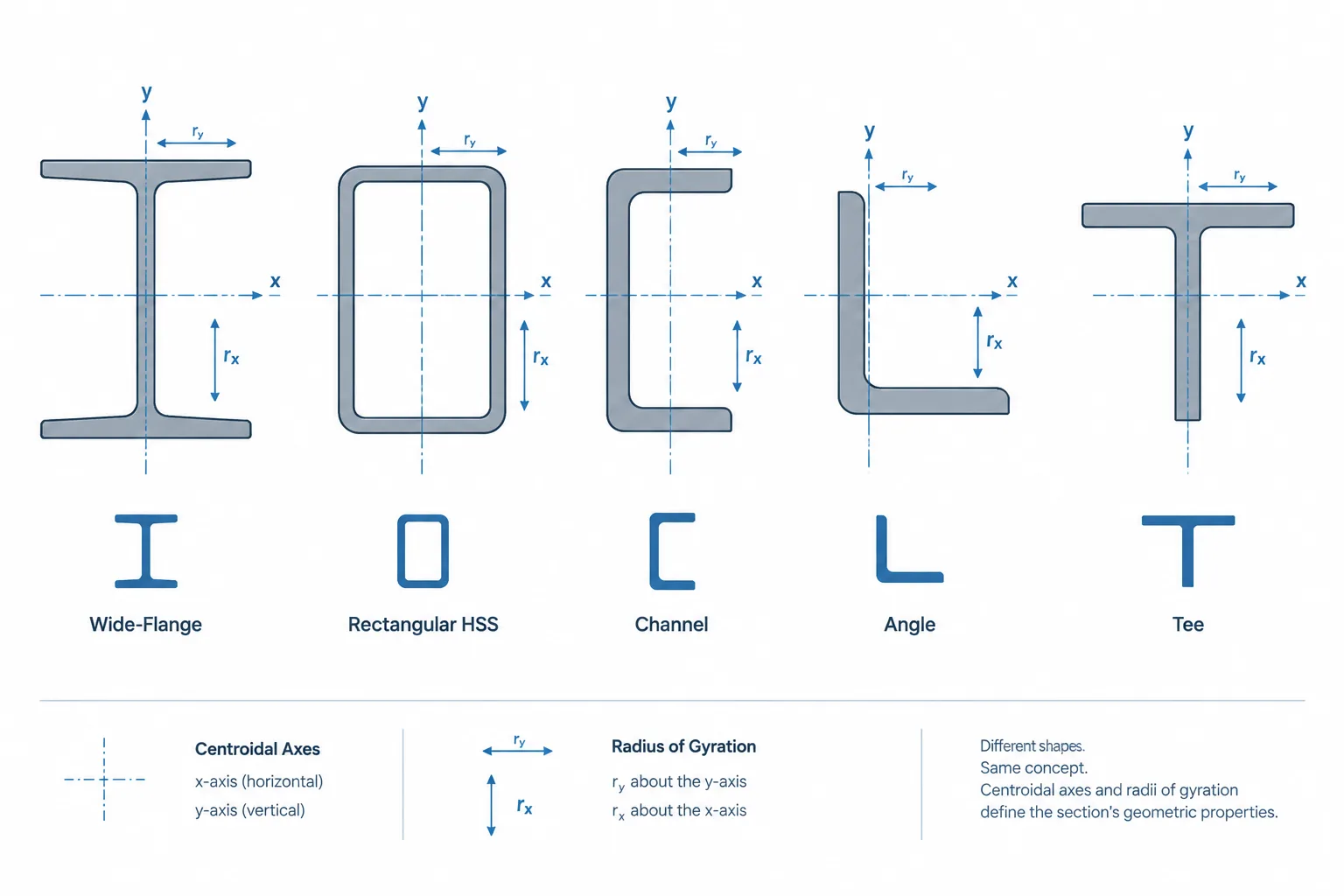
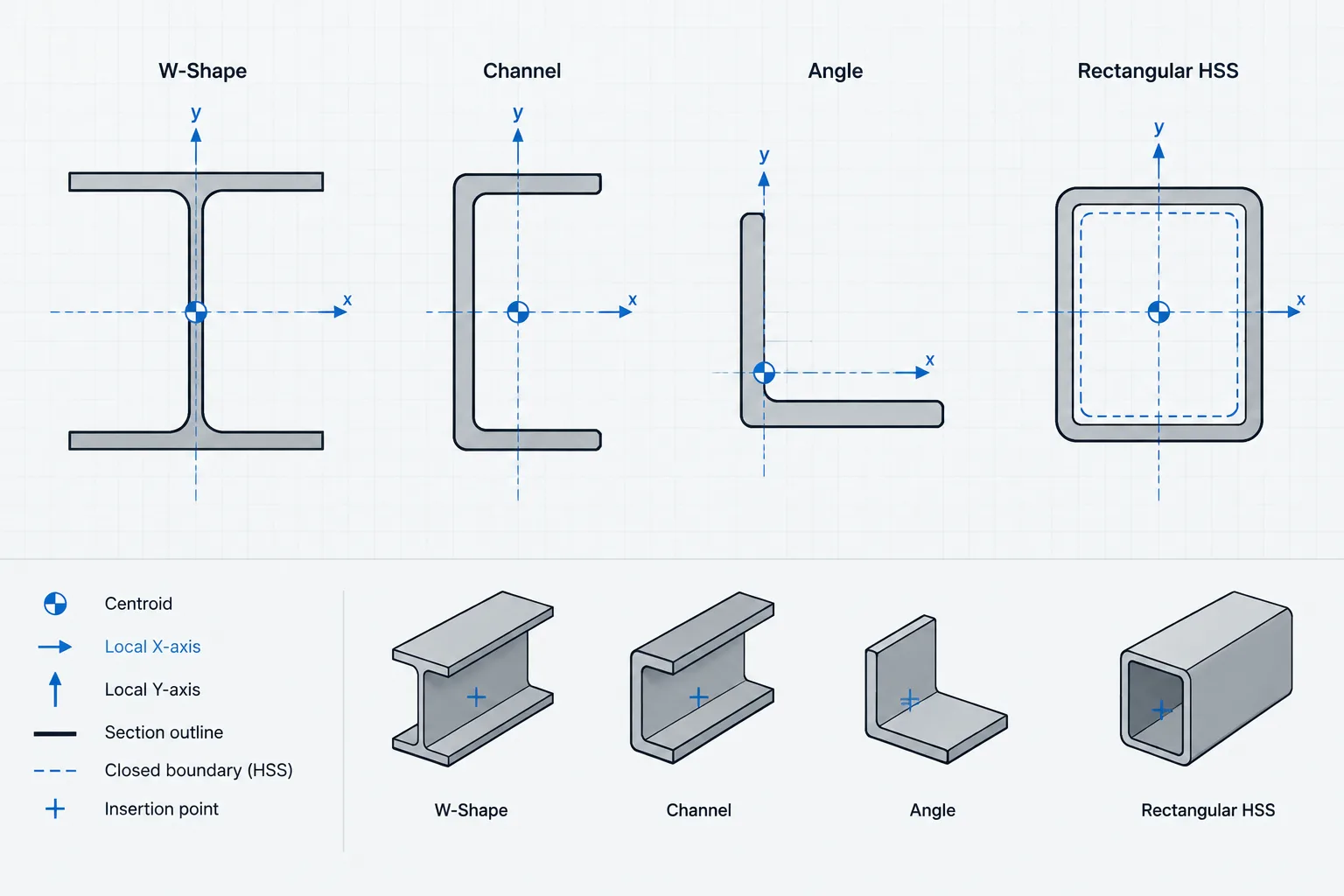
Splice detailing should begin with the two beam segments rather than with the connection plates. Establish the member work line, top-of-steel elevation, section orientation, end locations, and any slope or skew. Confirm whether both segments use the same shape and whether their flange and web geometry actually align.
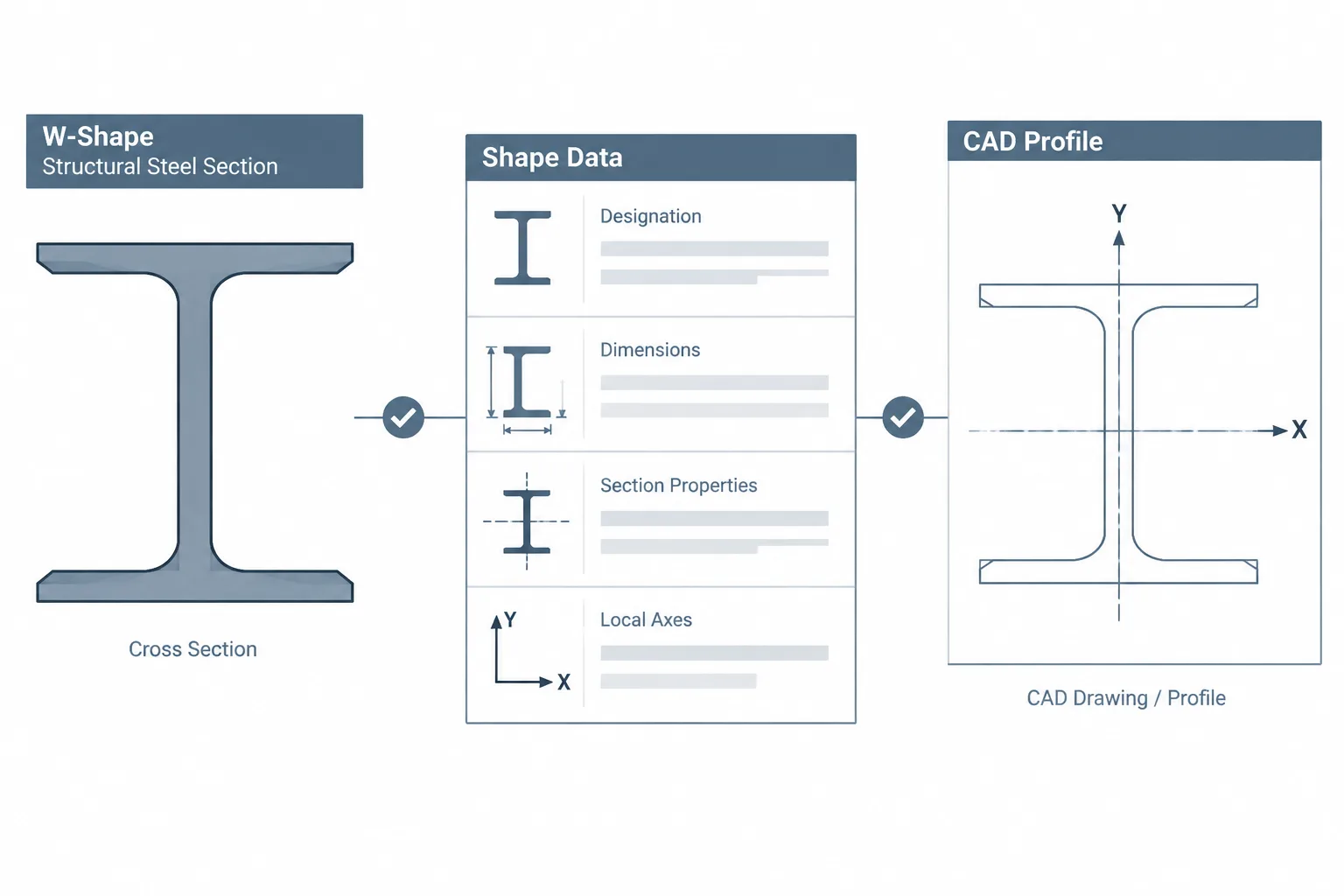
A shape change at the splice can introduce offsets between flange surfaces, web centerlines, or overall depths. Even beams within a related shape family should not be assumed to share identical flange thicknesses, web thicknesses, or clear web regions. Published and verified shape data should be used to model each member independently.
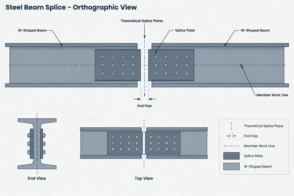
Useful Splice Datums
A clear datum system keeps the detail understandable and limits accumulated error. Typical references include:
- The beam work line or member centerline
- The theoretical splice plane
- Top of steel or another controlling elevation
- Web centerline or a designated web face
- Outside flange surfaces
- Bolt-group centerlines
The splice plane is especially important. It may represent the theoretical division between member segments, but the physical beam ends may be set back from that plane to provide a field gap. Drawings should distinguish the controlling splice location from the actual cut ends.
Splice Plane, Beam-End Gap, and Plate Overlap
The distance between the two beam ends affects erection fit-up, plate overlap, bolt positioning, and access. A nominal field gap should not be treated as leftover space created after the hole pattern is established. It is part of the connection geometry and must agree across the model, member details, assembly drawings, and erection information.
Detailers should verify:
- Whether the gap is centered on the theoretical splice plane
- Whether one member end is held while the other receives the adjustment
- How the gap changes plate overlap on each side
- Whether end preparation, coatings, or field conditions affect fit-up
- Whether erection tolerances or sequencing require additional coordination
Do not infer the gap solely from a schematic design sketch. If the controlling geometry is unclear, it should be resolved before member lengths and plate holes are released.
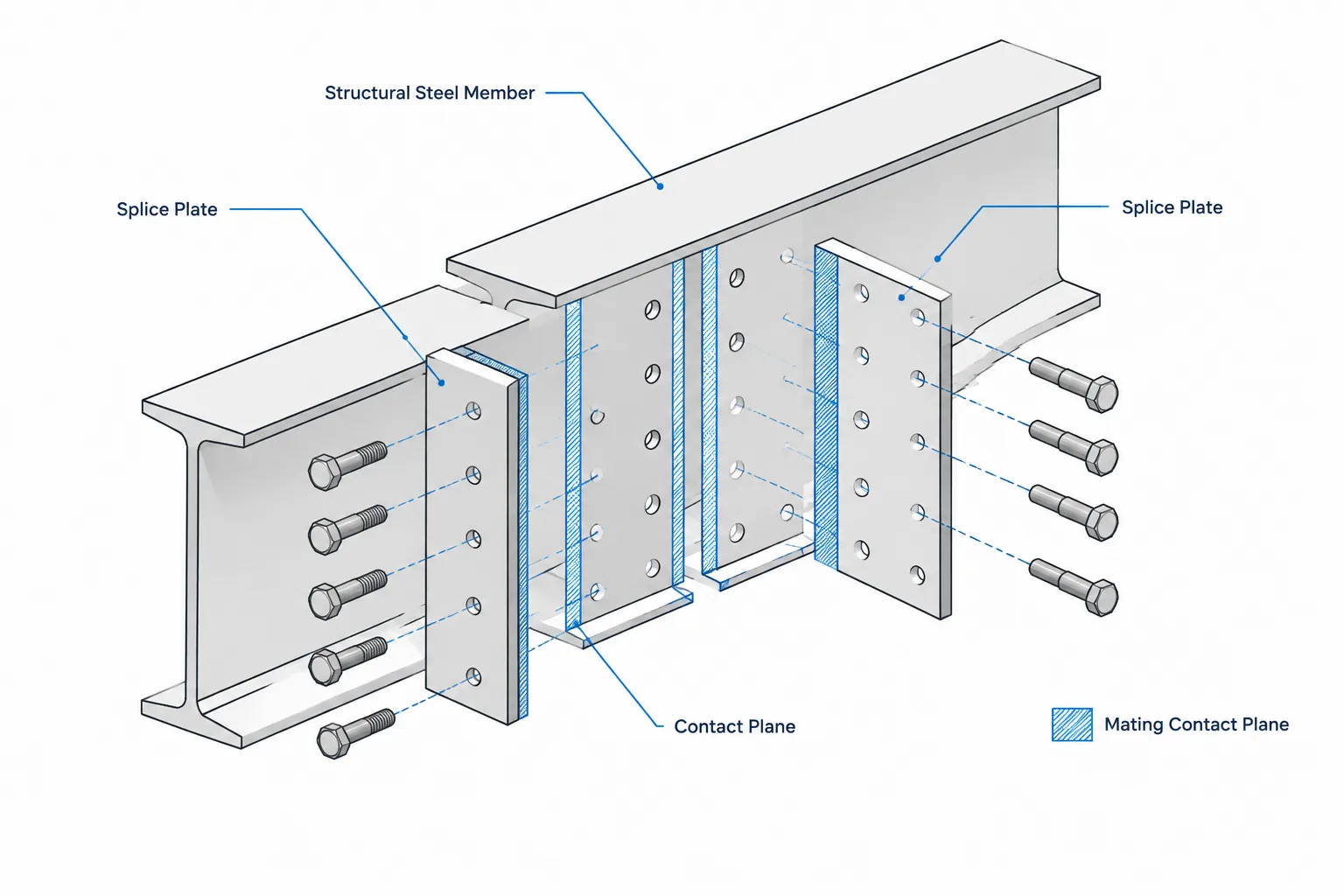
Web Splice Plate Geometry
Web splice plates occupy the clear region between the flanges and rolled fillets. Their width, edge shape, and placement must avoid unintended interference with the beam’s root geometry. A rectangular plate that appears to fit in a simplified line drawing may clash with rolled fillets in an accurate section model.
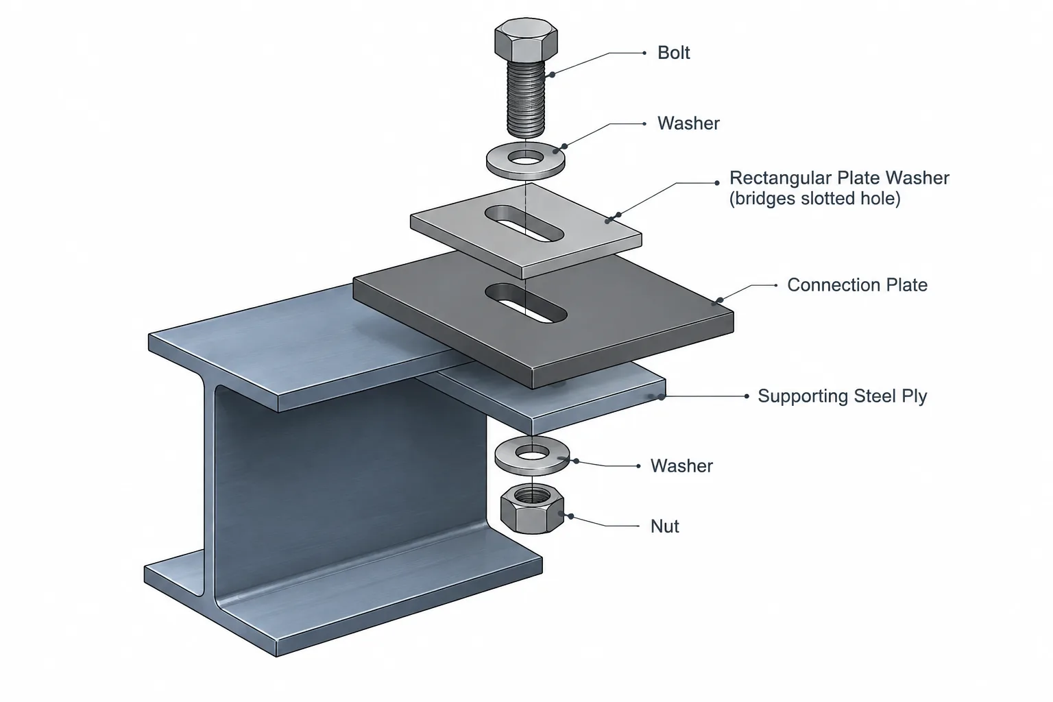
Important checks include plate-to-fillet clearance, bolt-head and nut clearance, weld access where applicable, and the relationship between holes and beam ends. For double-sided plates, the assembly stack includes the plate on one side, the beam web, and the plate on the opposite side. The bolt selection and detailing must correspond to the actual grip stack defined by the connection documents.
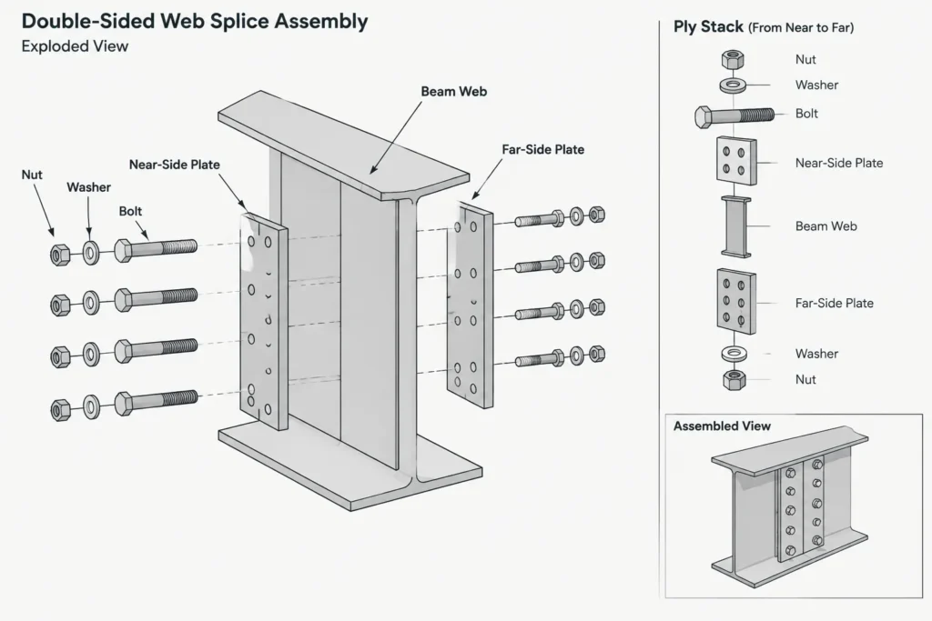
If the two beam segments have different web thicknesses or centerline positions, a single plate plane may not contact both members as expected. Fillers, offsets, or revised plate arrangements must not be improvised by the detailer; they require design coordination.
Flange Splice Plate Geometry
Flange splice plates require close attention to surface contact and surrounding obstructions. Exterior plates sit on the outer flange faces, while interior plates occupy the space between the flange and web. Interior plates may need to avoid web-to-flange fillets, and their available width can be limited by the section geometry.
The top and bottom flange assemblies should be detailed as distinct connection zones. They may not be identical, especially where the beam supports deck, slab, attachments, stiffeners, framing members, or other components near the splice.
For every flange plate, confirm:
- The face of the flange on which the plate is located
- The plate orientation and extent on each side of the splice
- The bolt rows associated with each member segment
- Clearance from the web, fillets, and adjacent connection material
- Access for bolt insertion, washers, nuts, and tightening equipment
- Whether nearby construction obstructs field installation
Bolt Layout: Treat Each Side of the Splice Deliberately
A symmetric-looking bolt pattern can encourage careless mirroring. Instead, define hole coordinates from stable datums and identify which holes belong to each beam segment. This is particularly important when member lengths, end setbacks, or plate overlaps differ across the splice.
Dimensions should make the following relationships clear:
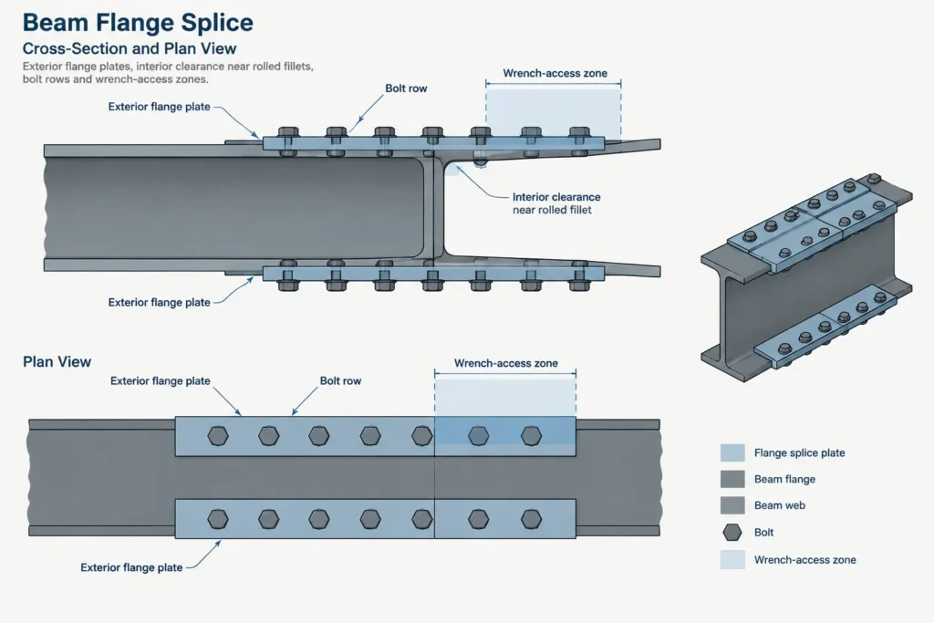
- Bolt lines relative to the web or flange centerline
- Rows relative to the splice plane or beam ends
- Hole locations in each plate
- Hole locations in each main member
- Any stagger, slot orientation, or intentionally unequal spacing
Slots and nonstandard holes should be shown only where required by the connection documents. Their orientation matters because a slot permits movement in a particular direction during fit-up or service, depending on the design. Plate geometry, washers, and installation notes must be coordinated with that intent.
Shop-Attached Versus Field-Installed Components
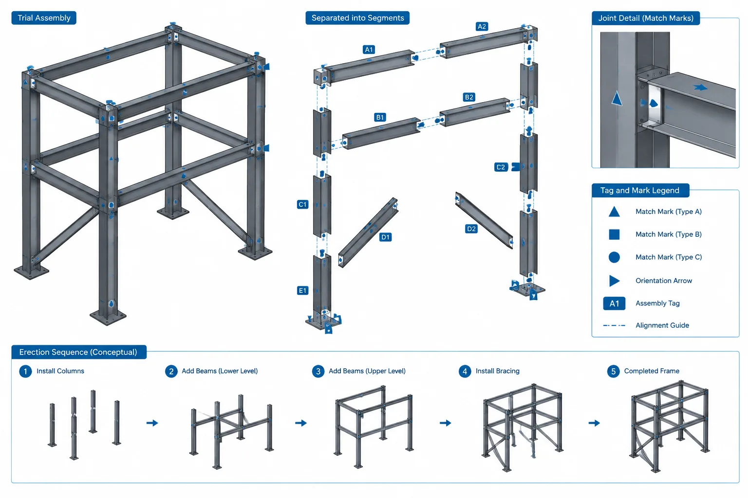
A splice drawing should communicate which pieces arrive attached to a member and which remain loose for erection. A plate shown in its final position is not automatically a shop-installed part.
Possible arrangements include plates shop-bolted to one beam segment, plates temporarily secured for shipping, loose plates shipped separately, or mixed assemblies in which some components are attached and others are field installed. The selected arrangement affects piece marks, bolt lists, shipping assemblies, erection access, and the sequence used to bring the members into alignment.
Temporary shipping bolts or erection aids should not be confused with permanent connection requirements. Any such provisions need clear identification and project-specific coordination.
Drawing Views That Make a Splice Understandable
| View | Primary information to show |
|---|---|
| Beam elevation | Splice location, beam ends, plate lengths, longitudinal bolt spacing, and member marks |
| Cross-section | Web and flange plate positions, ply stack-up, section orientation, and transverse bolt lines |
| Plan or flange view | Flange plate width, bolt gage, adjacent framing, and installation access |
| Exploded or isometric view | Plate relationships, loose pieces, and assembly sequence when orthographic views are ambiguous |
Not every splice requires every view, but the final drawing set should remove ambiguity about near-side and far-side plates, top and bottom components, shop and field work, and the orientation of each loose part.
CAD and Model Coordination Workflow
- Verify both beam shapes. Use controlled section data and confirm orientation, depth, flange thickness, web thickness, and fillet zones.
- Set the work points and splice plane. Establish the member coordinate system before adding connection material.
- Model the actual end setbacks. Preserve the distinction between theoretical member geometry and physical cut ends.
- Add plates by contact face. Avoid placing plates from arbitrary global coordinates when they should follow beam surfaces.
- Lay out holes from documented datums. Check the plate holes and member holes as separate fabrication items.
- Review the full ply stack. Include fillers, washers, coatings, and other components identified by the project documents.
- Run interference checks. Examine fillets, stiffeners, deck, adjacent beams, connection material, and wrench space.
- Compare every output. The model, shop drawings, plate details, bills of material, and CNC data should describe the same assembly.
Final Detailing Checklist
- Is the structural purpose of the web and flange components understood?
- Are both beam shapes and orientations verified?
- Is the splice plane clearly distinguished from the beam-end gap?
- Do plates clear rolled fillets and adjacent attachments?
- Are near-side, far-side, top, bottom, interior, and exterior plates identified?
- Are hole coordinates controlled from consistent datums?
- Does the modeled bolt grip match the complete ply stack?
- Can bolts be inserted and tightened in the intended sequence?
- Are shop-attached and field-installed items clearly separated?
- Do member details, part details, erection drawings, and material lists agree?
A reliable bolted beam splice detail is not merely a plate-and-bolt diagram. It is a coordinated description of member geometry, load-transfer components, fabrication datums, field fit-up, and erection access. Establishing those relationships early produces clearer drawings and reduces the chance that a small geometric assumption becomes a shop or field conflict.